V5−A/05/14V5−A/05/14V5−A/05/14
Instruction Manual w VERTICUS 5 Compressor Units
A-19
7. SAFETY VALVES
All compressor stages are protected by safety valves.
The adjustment of the safety valves is as follows:
Com
pressor
block
1st
stage
2nd
stage
3rd
stage
4th
stage
5th
stage
IK12.14 5 bar 24 bar 95 bar 450
bar
---
IK150 5.5 bar 24 bar 80 bar 350
bar
---
IK15.1 5.5 bar 24 bar 80 bar 350
bar
---
IK15.11 5.5 bar 24 bar 100
bar
420
bar
---
IK180 5.5 bar 24 bar 95 bar 350
bar
---
IK18.1 5.5 bar 24 bar 80 bar 180
bar
500
bar
The safety valves are adjusted to the corresponding pres
sure and sealed at the factory.
The safety valve for protection of the last stage is adjusted
according to order, see 1.3, Technical Data, but maximally
to the values given above.
8. PRESSURE GAUGES
The pressure in the final compressor stage can be mon
itored by means of the B-CONTROL display. See chapter
11. Pressure gauges in the instrument panel are optional ex
tras for all Verticus 5 units. If provided, the gauges should
indicate the correct pressures during operation.
8.1. INTERMEDIATE PRESSURE GAUGES
The correct values are given in chapter A-13.1., Technical
Data.
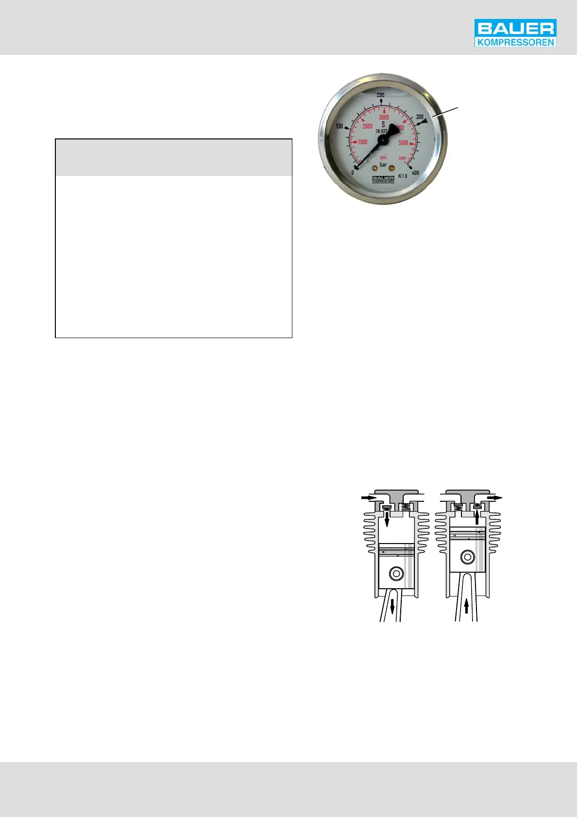
8.2. FINAL PRESSURE GAUGE
The final pressure gauge shows a mark indicating the max
imum operating pressure.
final pressure mark
Fig. 19 Final pressure gauge
8.3. OIL PRESSURE GAUGE
Correct oil pressure indication should read approx. 4.5 bar
(3 to 6 bar) .
If not, check the lube oil circuit or adjust the oil pressure. See
chapter D-2.
For oil pressure monitoring, see chapter A-11.
9. VALVES
The valve heads of the individual stages form the top part
of the cylinders. The intake and pressure valves are fitted in
side the valve heads.
Note that the valves are operated by the flow of the me
dium. On the suction stroke, the intake valves open and the
medium flows into the cylinders. At the start of the com
pression stroke the intake valve closes and the medium
opens the pressure valve, Fig. 20.
Intake and pressure valve of the 1st stage is a combined
plate valve under the valve head (Fig. 21). Different valve
types are used as shown.
Fig. 20 Valve operation
Intake Pressure