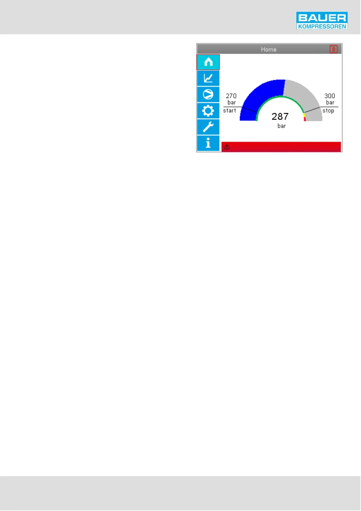
Fig. 37 Start page
Emergency off pressed
Instruction Manual w VERTICUS 5 Compressor Units
A-31
Menu and navigation
The LCD display contains important information concer
ning the combination installation.
Start page
Fig. 37. This page is displayed after booting the control sys
tem. The page continues to be displayed as long as no menu
operation has been carried out. If no menu operation is car
ried out, 10 minutes after the last operator step has been
carried out, the system jumps back to this page and logging
out takes place automatically.
The main constituent of the start page is the final pressure
display as a quasi-analogue arc display and with the digital
display located centrally in the arc. The current pressure is
shown by the blue arc increasing in intensity from the left
(0 degree position) to the right (180 degree position). In the
180° arc the start value of the compressor and the stop va
lue of the compressor (reference point 1) are each shown
by a line.
The inner arc is shown in green from 0° to the stop point,
in yellow from the stop value to the top switching point of
the sensor channel selected under regulating point 1, and
in red from there to the 180° end of the scale.
There is a digital residual fill display under the final pressure
display. The expected time required is constantly calculated
from the pressure increase per unit time as soon as the com
pressor is running and the display is adapted accordingly.
The residual filling time display only becomes active when
an actual pressure increase can be measured. In the period
after starting the compressor, no pressure increase can be
expected, because of the system characteristics, since we
first fill the filter vessel and the final separator in the system
before the pressure increase can be measured after the
pressure retention valve on the pressure sensor. In this pe
riod the digital time display shows an egg-timer.On the
top right we show the consumption degree of the filter by
a symbolic filter cartridge. The symbol empties segment by
segment in accordance with the filter saturation calculation
and the SECURUS measurement.When the SECURUS pre-
warning limit is reached, the symbol is shown in orange;
when the SECURUS saturation limit is reached, the symbol
is shown in red.
Right at the bottom we show the last active alarm that was
created, i.e. the extract of the top line of the current mes
sage list.
If the alarm is an error, the background colour is red, if the
alarm is a warning, the background colour is yellow. The
line is not visible if there is no alarm.