Components
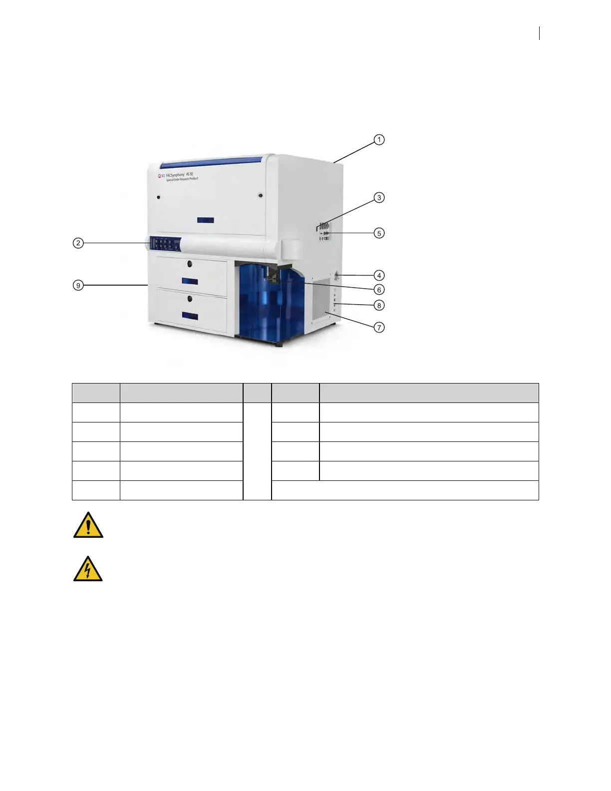
The following figure shows the main components of the instrument. Each component is described in detail in
the following sections.
Number Component Number Component
1 Heat ventilation slots (top) 6 Sample injection port (SIP)
2 Control panel 7 Heat ventilation slots (side)
3 Power button 8 Air and fluidic ports
4 Electrical plug 9 Optics access doors (cacadagon detector arrays)
5 Fluidic sensors
Do not place any objects on top of the instrument. Blocking the ventilation may cause the instrument to
overheat.
Do not place liquids on top of the instrument. Any spill of liquid into the ventilation openings could cause
electrical shock or damage to the instrument.
Chapter 2 Introduction 13