About laser delay
Introduction
This topic describes how to manually set the laser delay if you are not using CS&T for cytometer setup and
tracking.
About laser signal delay
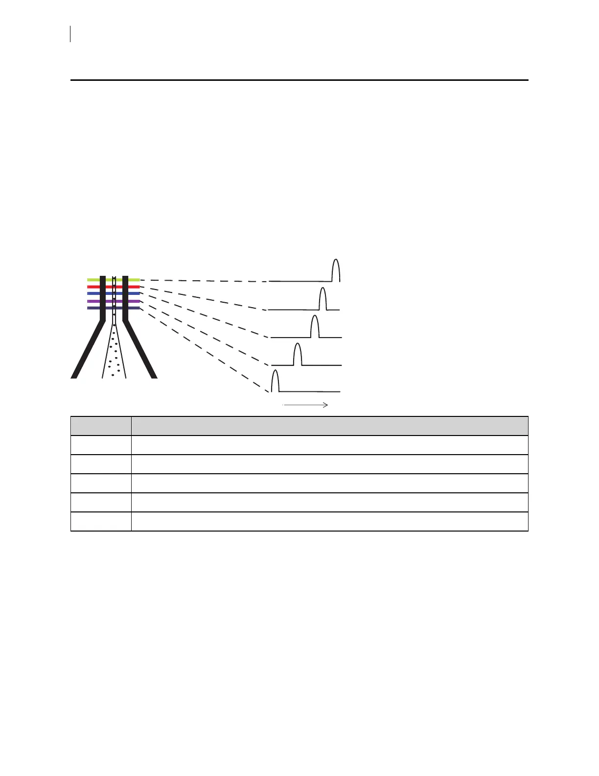
Sample interrogation takes place within the cuvette flow cell. Laser light is directed through lenses that focus
multiple lasers on the event stream at different positions. This allows optimal detection of fluorescent signals
from each laser with minimal cross-contamination from the other beams.
Because the laser signals are spatially separated, there is a slight delay between the detection of each laser’s
signal.
Item Number Laser Delay
1 UVlaser (shortest)delay
2 Violet laser delay
3 Blue laser delay
4 Red laser delay
5 Yellow-green laser (longest)delay
The laser delay setting in BDFACSDiva™ software is used to re-align the signals so they can be measured and
displayed on the same time scale, ensuring that the signals from each laser are assigned to the proper event.
The reference laser is positioned in the middle of the order to reduce the maximum compensation delay values
that need to be applied by the software, which improves stability. The blue laser, as reference, will have a 0
delay value, the red laser will have positive delay compensation, and the UVlaser will have negative delay
compensation.
94 BD FACSymphony™ A5 SE User's Guide