Appendix A: Technical Overview 133
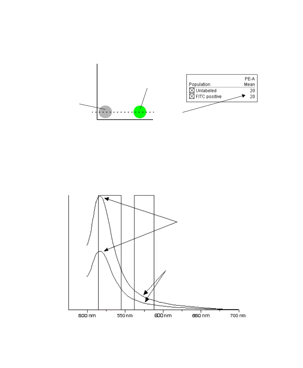
Compensation is optimal when the positive and negative FITC populations have
the same means or medians in the PE parameter statistics (Figure A-8).
Figure A-8 FITC spillover optimally compensated out of the PE parameter
Once fluorescence compensation has been set for any sample, the compensation
setting remains valid for a subsequent dim or bright sample, because
compensation subtracts a percentage of the fluorescence intensity. Figure A-9
illustrates this principle. Although the signals differ in intensity, the percentage of
the FITC spillover into the PE detector remains constant.
Figure A-9 Two FITC signals of different intensity
PE
FITC
means match
unstained
particles
FITC positive
population
FITC PE
different intensity FITC signals
same proportion or percentage of
spectral overlap in PE channel
normalized intensity
LSR2.book Page 133 Tuesday, April 25, 2006 3:34 PM
 Loading...