113
it 180º around its longitudinal axis. The programme itself requires the user to place the lamp in the two possible
positions and check in which of the two maximum light intensity is obtained in the optical system.
5.1.4.9. Changing an optical lter
a) Access the Filter Wheel Conguration screen of the user or service programme. Indicate which lter is to be chan-
ged (position 1-9) and click on the Change lter button.
b) Remove the rotor cover.
c) Remove the lter wheel cover by simply pulling on it.
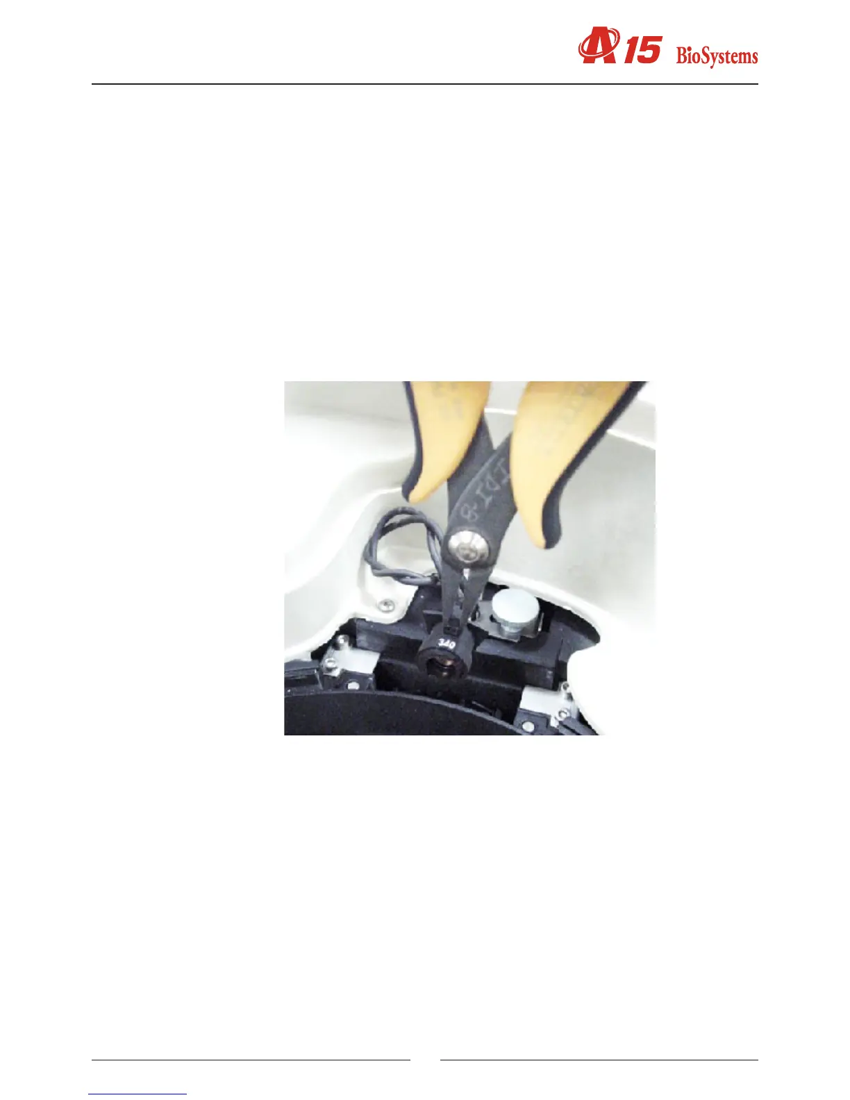
d) Remove the top lter using a pair of ne pliers.
e) Position the new lter by pressing down until it is correctly in place.
f) Do not leave the position free without putting a lter holder in place. If no lter is required in this position, put a
covered lter holder in place.
g) Ret the lter wheel cover. Put the rotor cover back.
h) If it is different, introduce the wavelength of the new lter that has been installed.
5.1.4.10. Conguration of the lter wheel
a) Remove the rotor completely. Remove the insulation.
b) Remove the cover (1).
c) Loosen the Allen bolt that holds the lter wheel in place (2).
d) Remove the motor (3). On removing the motor, joined to the wheel axle, the wheel comes free.
e) Place the new lter wheel in position and introduce the motor with the axle in position. The Allen bolt must coincide
with the machined area of the axle. Put screwfastener on the bolt.
f) Fit the wheel to the axle. Check that the rotor turns freely without mechanical interference.
5.1.4.11. Changing the lter wheel start photosensor
See the gure in the previous section.
a) Remove the complete rotor.
b) Remove the cover (1).
d) Remove the start photosensor board (3). Unsolder this board from the electrical hose and solder the new one.
e) Ret the system and check that the wheel turns freely.