Service manual
40
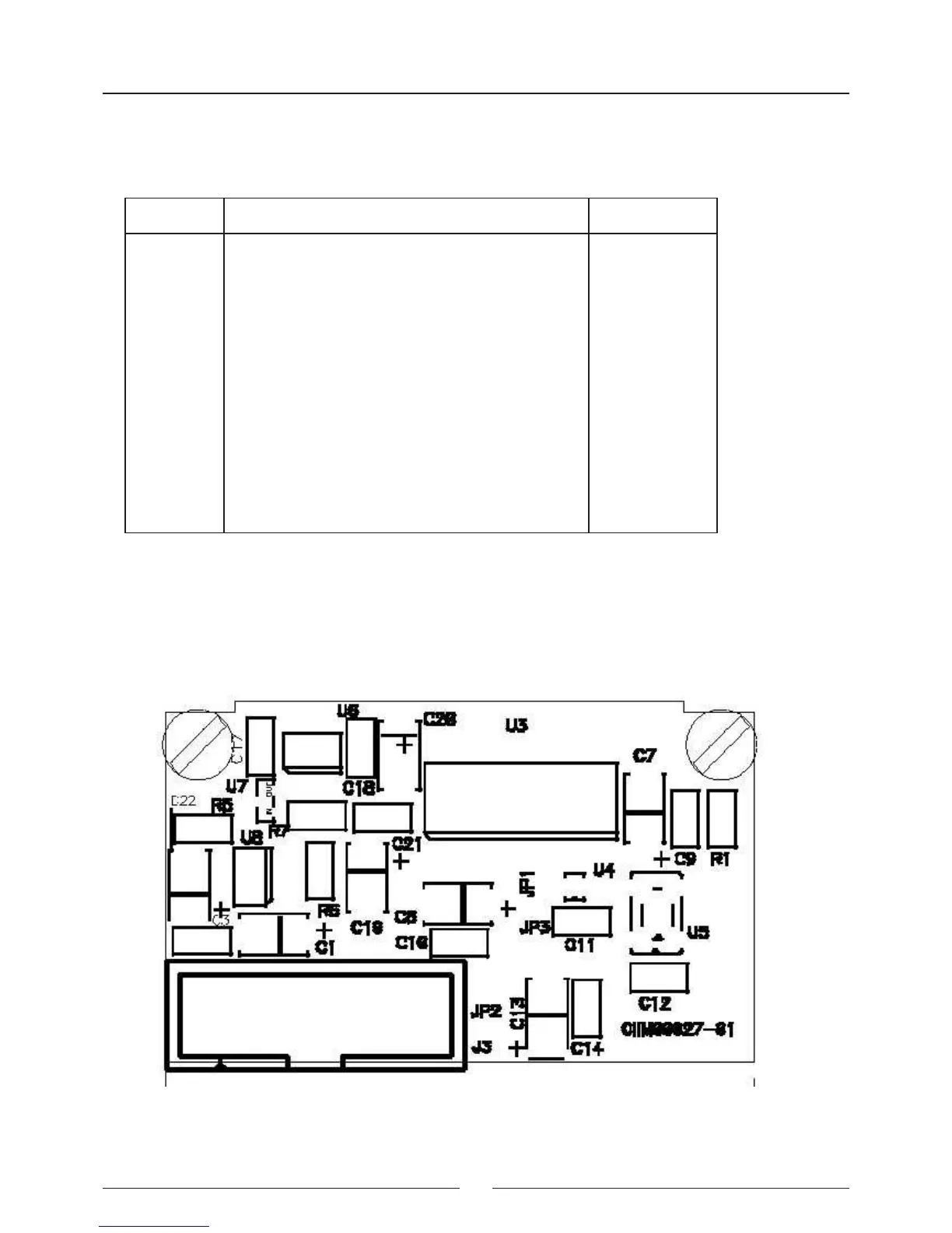
3.4 Photometry Board (CIIM00027)
This board also has the heart of the absorbance measuring system for the samples to be analyzed. It is made up of
a photosensor and an associated analogical-digital conversion circuitry (DDC112).
JP1 - soldering bridge - Solder only if the local oscillator and the U4 and U5 scales, respectively, are not present.
JP2 - soldering bridge - as per JP1
JP3 - soldering bridge - joins together the analogical and digital frames
Connector Function Pins
J3 Photometric board connection CIIM00029) 1 - 12 V
2 - GND
3 - DVALID
4 - DCLK
5 - DOUT
6 - DXMIT
7 - RANGE2
8 - RANGE1
9 - RANGE0
10 - TEST
11 - CONV
12 - GND
13 - CLKAD
14 - GND
15 - GND
16 - V DC