27
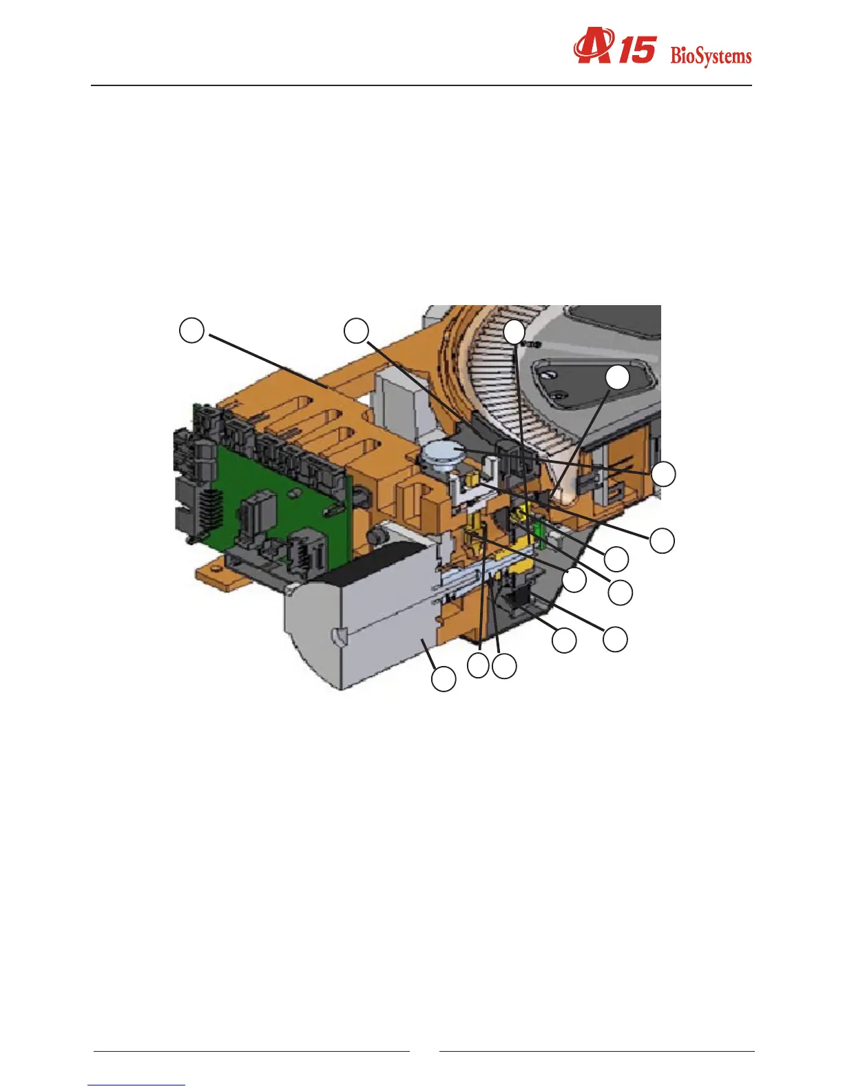
The aluminium body (1) is the structure that supports all the elements of the lighting system. The lamp holder (2),
fastened to the body by means of the fastening system (4), keeps the halogen lamp (3) in position without the need
for adjustments. The lter drum (5) has 10 positions for optical lters. Position 0 must always be taken up by a cove-
red lter. The other positions can be taken up by an interferential lter (8) or by other covered lters. No position in
the drum must be left unoccupied. Each lter is tted on a lter holder (6) and fastened to it by the nut (7). The lter
holders can be dismounted from the drum by simply pulling on them. The cover (13) allows easy access to the lter
drum. The lter drum is fastened to the axle (9). This axle can be turned by the direct action of the motor (11). Its end
is guided by the bearing (14). The photosensor (10) indicates the start position of the drum. The light from the lamp,
limited by the diaphragm (12). The light passes through the lter drum, which selects the desired wavelength, and
through the aperture(15), which adapt the form of the light beam to the geometry of the rotor wells.
2.2.4. Electronics cover
(1) BACK COVER OF THE ELECTRONICS
(2) MAINS SWITCH
(3) FUSE HOLDER
(4) ID LABEL
(5) NETWORK CONNECTOR
(6) COM1 CONNECTOR
(7) COM2 CONNECTOR
(8) HINGES
The metal cover (1) supports the mains switch (2) and the fuse holders (3), as well as the identication label (4). The
COM1 and COM2 connectors (6, 7) and the mains connector (5) are fastened to the electronics box. The cover(1)
opens on 2 hinges (7).
1
2
4
3
5
8
7
13
6
9
11
12
14
15