21
(14) 3-CHANNEL ELECTROVALVE
(15) ELECTROVALVE NUT
The plastic body (1) joins the different elements that make up the pump. The transparent methacrylate uidic chamber
(2) makes it possible to observe the ow of liquid through the pump. The support (4) fastens the seal (3). The ceramic
piston (5) dispenses by displacing a certain volume of liquid in the chamber. The piston is adhered to the support (6),
which moves alternatively by the rotation of the endless screw (9) xed to the motor axle (10). The barrier (7), joined
to the piston support, obstructs the photosensor (11) when the piston reaches its start position. The axial bearing
(8) prevents any longitudinal displacement of the motor axle for greater precision in the dispensing operation. The
3-channel electrovalve (14) makes it possible to connect the pump chamber to the distilled water container or to the
thermostated needle. The Teon tube (13) connects the chamber to the electrovalve. It is connected to each of these
elements by the nuts (13) and (15).
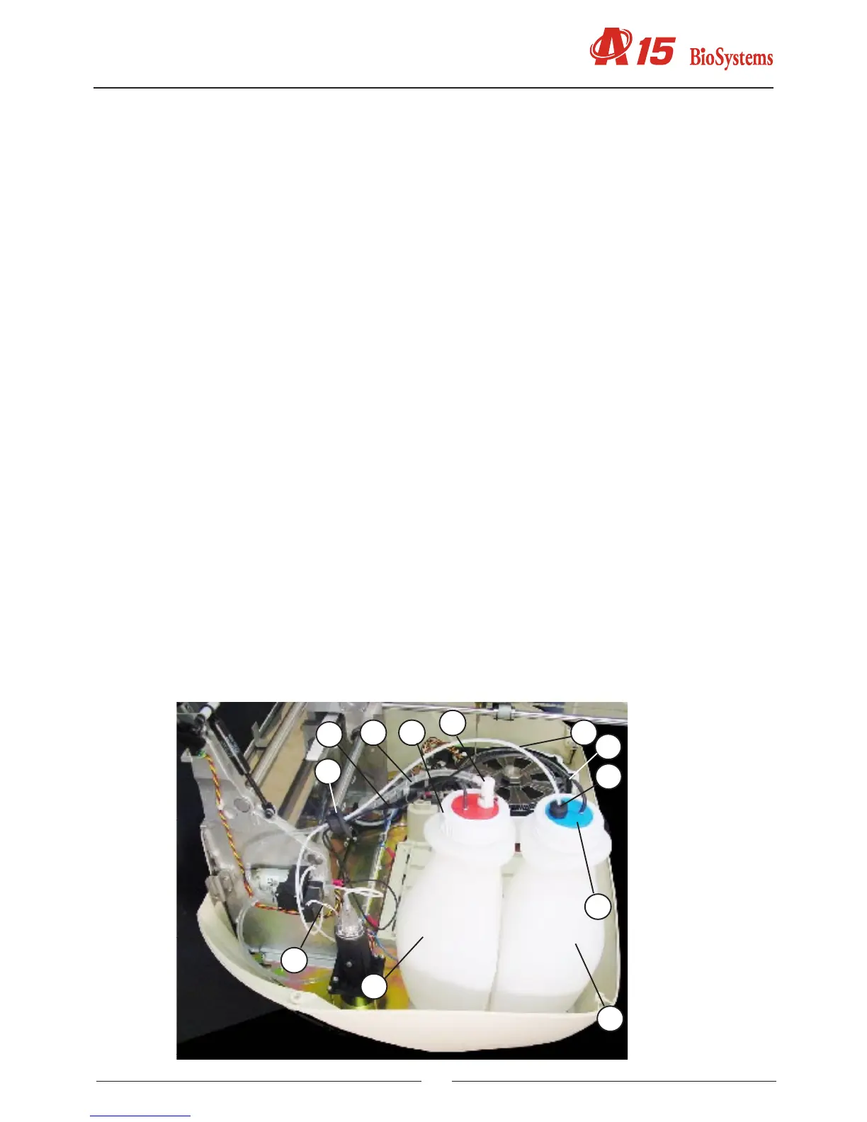
2.2.2.3. Tubes and containers
(1) WATER CONTAINER
(2) WATER CONTAINER LID
(3) WATER CONTAINER TUBES FASTENING
(4) WATER CONTAINER TEFLON TUBE
(5) TEFLON TUBE FILTER
(6) ELECTROVALVE NUT
(7) SYSTEM LIQUID LEVEL SENSOR CABLE
(8) LEVEL SENSOR
(9) WASTE CONTAINER
(10) WASTE CONTAINER LID
(11) FAST COUPLING NUT
(12) WASTE CONTAINER PVC TUBE
(13) GROMMET
(14) WASTE LEVEL SENSOR CABLE
The Teon tube (4) connects the distilled water container (1) to the electrovalve of the dispensing pump. This tube is
installed at the end of the lter container (5). It is connected to the electrovalve of the dispensing pump through the nut
(6) The Teon pipe passes through the rubber piece (3) in the lid (2) of the container, which fastens them in position.
The PVC tube (12) connects the waste extraction membrane pump to the waste container (9). The waste container
lid (19) has a fast coupling nut (11) with automatic drip-proof closing when disconnected. All the tubes pass into the
interior of the analyzer through the rubber grommet (13).
1
3
2
4
6
7
9
10
11
12
13
14