Service manual
16
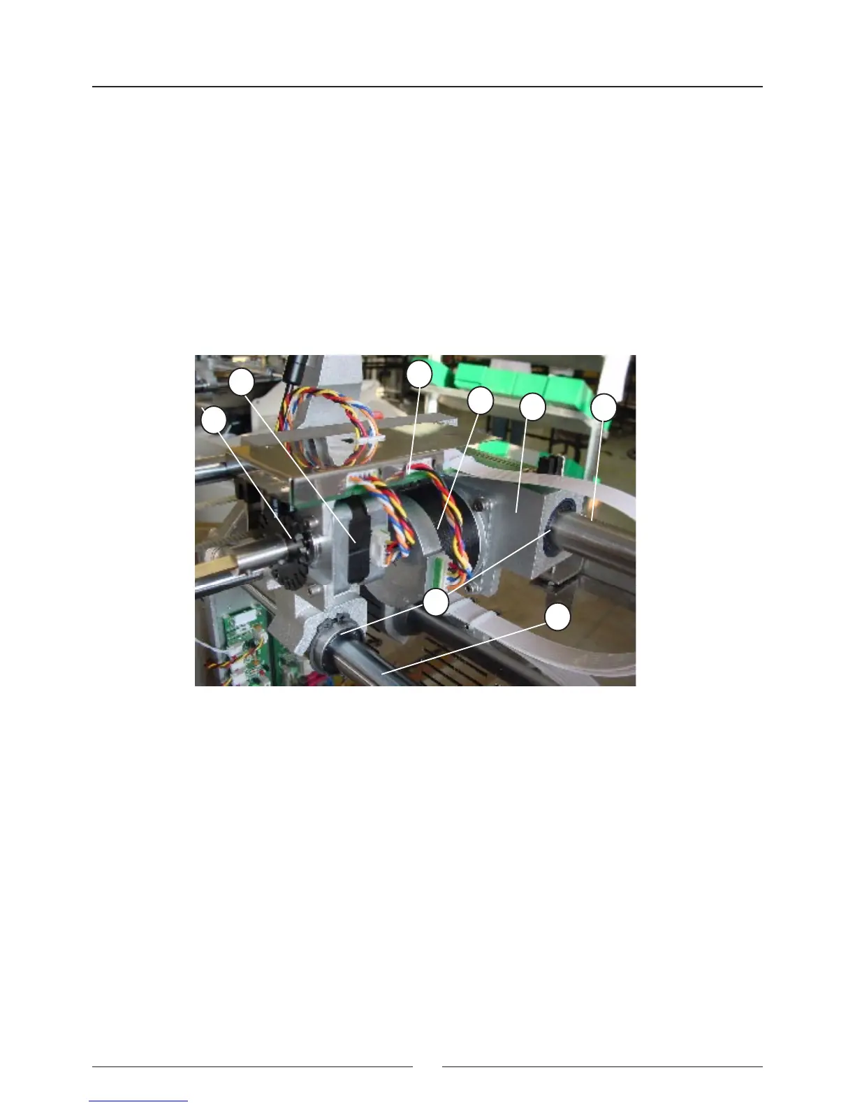
2.2.1.2. X Carriage
(1) X CARRIAGE BODY
(2) UPPER X AXIS - RACK
(3) LOWER X AXIS
(4) X MOTOR
(5) Z MOTOR
(6) ENCODER
(7) XYZ INTERCONNECTION PCB
(8) BEARINGS
The X carriage body (1) moves along the two axes (2, 3). The upper axis (2) acts as a rack. The X motor (4) is tted
with a pinion that moves the carriage. The X carriage also supports the interconnection PCB (7) and the Z motor (5).
To enable the movement, it uses linear bearings (8).
2.2.1.3. Y Carriage
(1) Y CARRIAGE BODY
(2) Y GUIDE AXES
(3) Y MOTOR
(4) BELT
(5) BELT RETURN PULLEY
(6) START PHOTOSENSOR
(7) START TAB
(8) NEEDLE UNIT
(9) BEARINGS
The body of the Y carriage (1) moves along the two axes (2) on linear bearings (9). The said axes are supported by
the X carriage. The movement is made by the Y motor (3) by the belt (4) and the return pulley (5). The start of the
movement is controlled by the tab (7) and the start photosensor (6) located on the X carriage (10). The body of the Y
carriage (1) also supports the needle unit.
1
2
3
4
5
6
7
8