Service manual
18
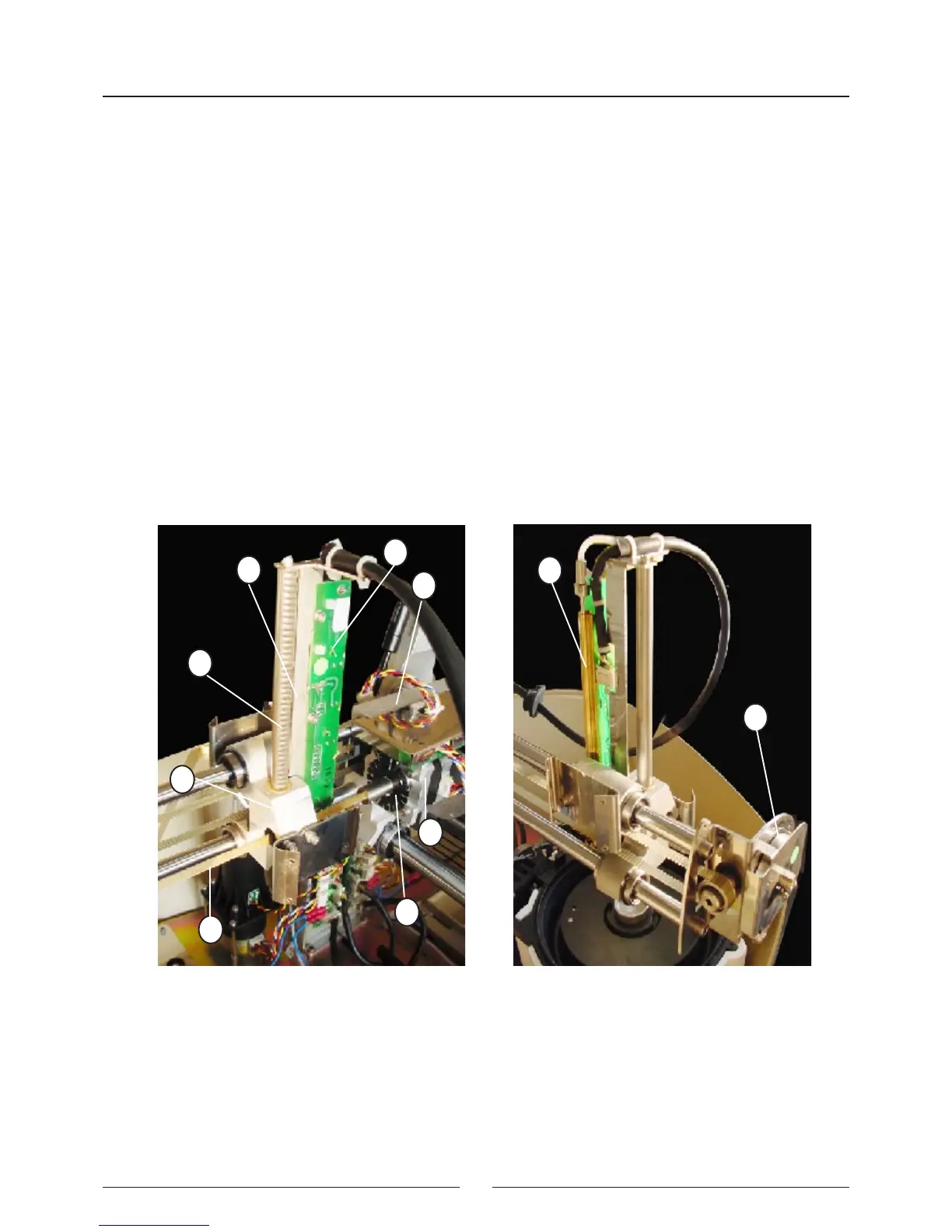
2.2.1.4. Needle unit
(1) Z GUIDE
(2) RACK
(3) Z MOTOR
(4) ENCODER
(5) TRANSMISSION AXIS
(6) RETURN SPRING
(7) THERMOSTATATION PIPE
(8) CONTROL PCB
(9) Y CARRIAGE
The Z guide (1) supports the thermostatation pipe (7) and the control PCB (8) where the heating elements are located,
together with the thermistor signal amplier and level detection and the Z axis start photosensor. The rack (2) supports
the Z guide (1) which crosses the Y carriage (9) on two bearings. The Z motor (3) is fastened to the X carriage (10)
and is moved by a transmission axis (5) tted with a pinion that acts on the rack. The return spring (6) acts on the
transmission axis and prevents the needle from falling in the event of a power cut: The encoder (4), which detects any
obstruction to the movement of the thermostated needle (9) is located on the same axis and on the part of the motor.
3
1
10
5
4
8
7
6
2
9