65
Adjustment of Z-axis of tubes
When the adjustment of the tray of pediatric racks is selected, it appears another adjustment: the Z relation
between pediatric and tube.
In order to carry out this adjustment, follow the following steps:
1. Place a diameter 15 rack in position 2 of the tray, with a tube in rack position 1.
2. Insert a value in the box of Z pediatric-tube relation. This value shows the separation steps between a pe-
diatric well and a primary tube.
3. Press Start.
4. Check that the probe has not collided to the bottom of the tube.
5. Move the probe by Z movements (screen or keyboard) until it reaches the well bottom.
6. Once the adjustments are nished, adjustments have to be kept in the instrument, so press Save.
4.2.4. Adjustment of the positioning of the rotor
This screen enables the adjustment of the positioning of the rotor with regard to the dispensing point and the
optical system. One or the other is selected by means of two different tabs.
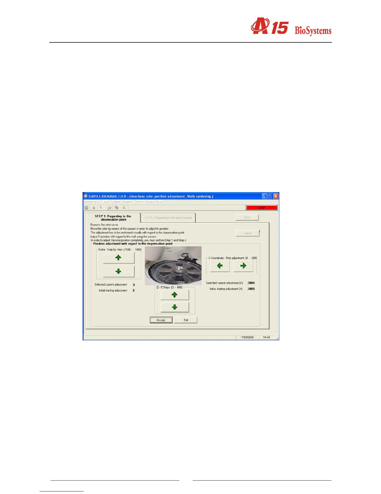
4.2.4.1. Centering of the rotor with regard to the dispensing point
The analyzer initialises the rotor and positions the rst rotor well at the currently programd dispensing position.
The technician has buttons to move the rotor step by step to adjust, if necessary, this position and buttons for
ner adjustment of the X coordinate over the dispensing point. At all times, the screen shows the current dis-
pensing coordinate on the rst well and of the X axis position, the last coordinate stored and the initial screen
input coordinate, as additional information for the technician. When this is satisfactory, the current coordinate
of the dispensing point of the rst well can be stored by pressing the Store button. Pressing the Cancel button
keeps the last stored value and the current value is not stored. Pressing the Restore button restores the initial
screen input value.
4.2.4.2. Centering of the rotor with regard to the optical system
This adjustment is necessary only if the Rotor Centering Adjustment has been carried out with regard to the
dispensing point (4.1.4.1.). This adjustment must be made with the rotor cover in position. The analyzer initia-
lises the rotor and lls the rst 3 wells of the rotor with distilled water. Next, step-by-step optical readings are