85
the luminosity of the photometric system. The lamp must be changed with the analyzer in sleeping mode. If
the analyzer is on standby mode, the program shuts it down automatically. The lamp must never be touched
with ngers. Once the new lamp has been installed and the covers of the optic and rotor put back, access the
change lamp utility and press the Test button. The program starts up the analyzer, checks the light intensity of
the optical system, shuts down the analyzer and then requests the technician to remove the lamp holder again
and replace it again turning it 180º on the axis of the lamp. If the temperature of the lamp holder is high, wait until
it cools down or use pincers to hold it. The program starts up the analyzer again, measures the light intensity
of the optical system again, compares the light intensity in both possible positions and chooses the greatest
luminosity. If it is the current position, it tells the technician that the test is complete. If the best position were
the previous one, the program shuts down the analyzer and asks the technician to remove the lamp holder and
replace it, turning it 180º on the axis of the lamp, returning the lamp to its initial position. If the option selected
at the beginning was to Check the Lamp, the process is the same but without shutting down the analyzer at
the beginning.
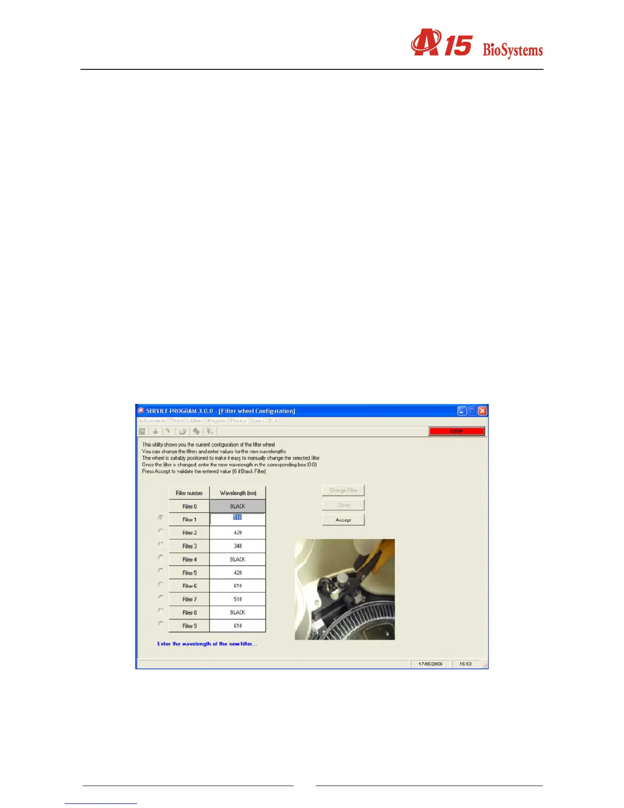
4.4.5. Conguration of the lter wheel
This screen enables the modication of the analyzer lter wheel. The wheel has 10 positions. Position 0 must
always contain a covered lter so that the analyzer can perform the darkness adjustment. Positions 1 to 9 can
be used for optical lters. All the positions of the wheel must be occupied for it to work correctly. The positions
that do not contain an optical lter must be occupied by a covered lter. The analyzer includes as standard 8
optical lters in positions 1 to 8 and two covered lters in positions 0 to 9. If one of the lters is to be changed,
select the desired position of the wheel and press the Change Filter button. The analyzer automatically posi-
tions the lter wheel appropriately so that the technician can change the lter through the window of the optical
system. Next, if it is different, introduce the wavelength of the new lter that has been installed. If the lter is
covered, introduce value 0. On closing the screen, the analyzer asks if the lters have actually been physically
changed and a series of warnings are given to the technician telling him he must bear in mind whether or not
he has changed a lter.
4.4.6. Demonstration mode
On pressing the Start button, the analyzer activates some of its mobile components, imitating functioning during
a work routine. The activated mechanical components are the operating arm, the reactions rotor and the lter
wheel. On pressing the Cancel button, the analyzer nishes the current cycle and returns to its rest position.