Service manual
36
TP1 - Lamp voltage from 5.75 V <6V
TP2 - 12V analogicals
TP3 - 5V digital
List of LED diodes:
D4 - Indicates 5V activated
D2 - Indicates 12V lamp activated
D3 - Indicates 12V analogicals activated
3.2 Power Supply Board (CIIM00015)
This is made up of 2 different switched regulators and 1 voltage line that enable distribution of the power supply in
accordance with the requirement of each subsystem.
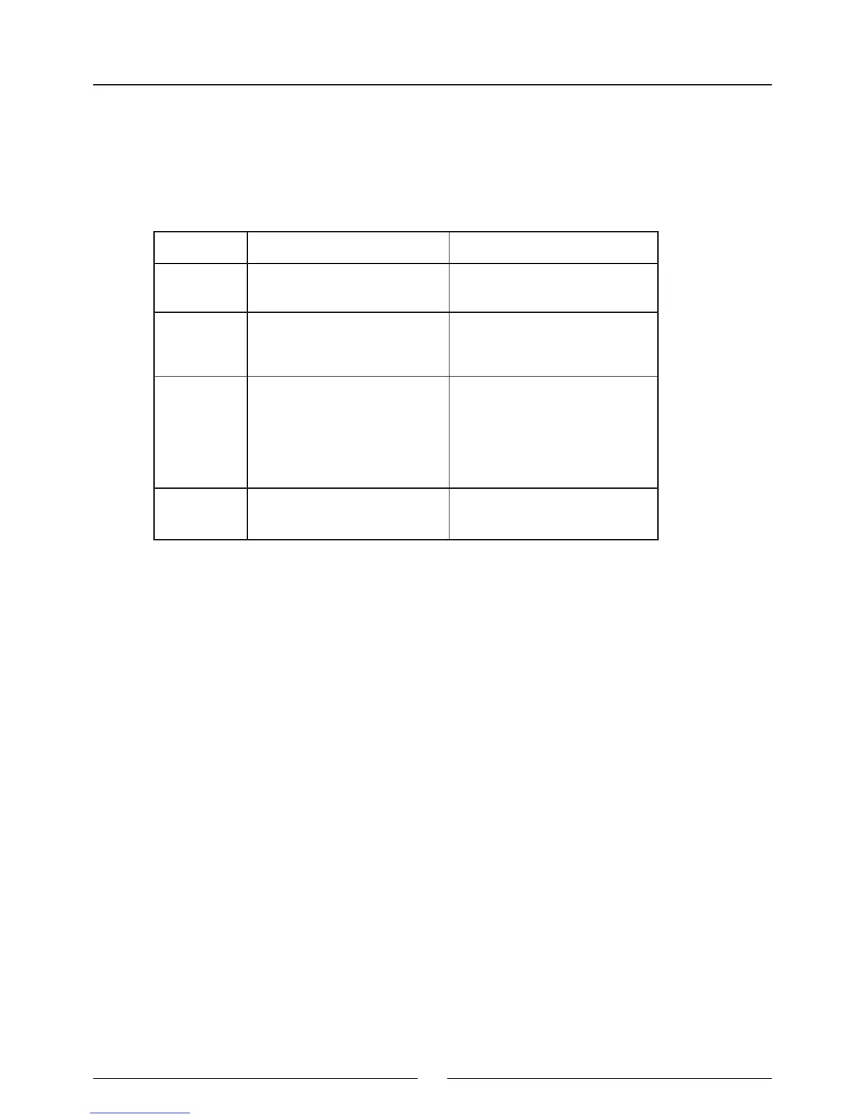
Connector Function Pins
J1 24 V input 1 - 24V
3 - (GND)
J2 Output voltage of 6 V for lamp
supply
1 - 12 V
3 - GND
J3 Output voltage of 24 V, 12V,
5 V and fan and lamp control
input
1 - 36V
2 - GND
3 - 12V
4 - 5V
5 - ENABLE LAMP
6 - ENABLE FAN
J4, J5 Fan output voltage of 24 V 1 - 24V
2 - GND