66
Service manual
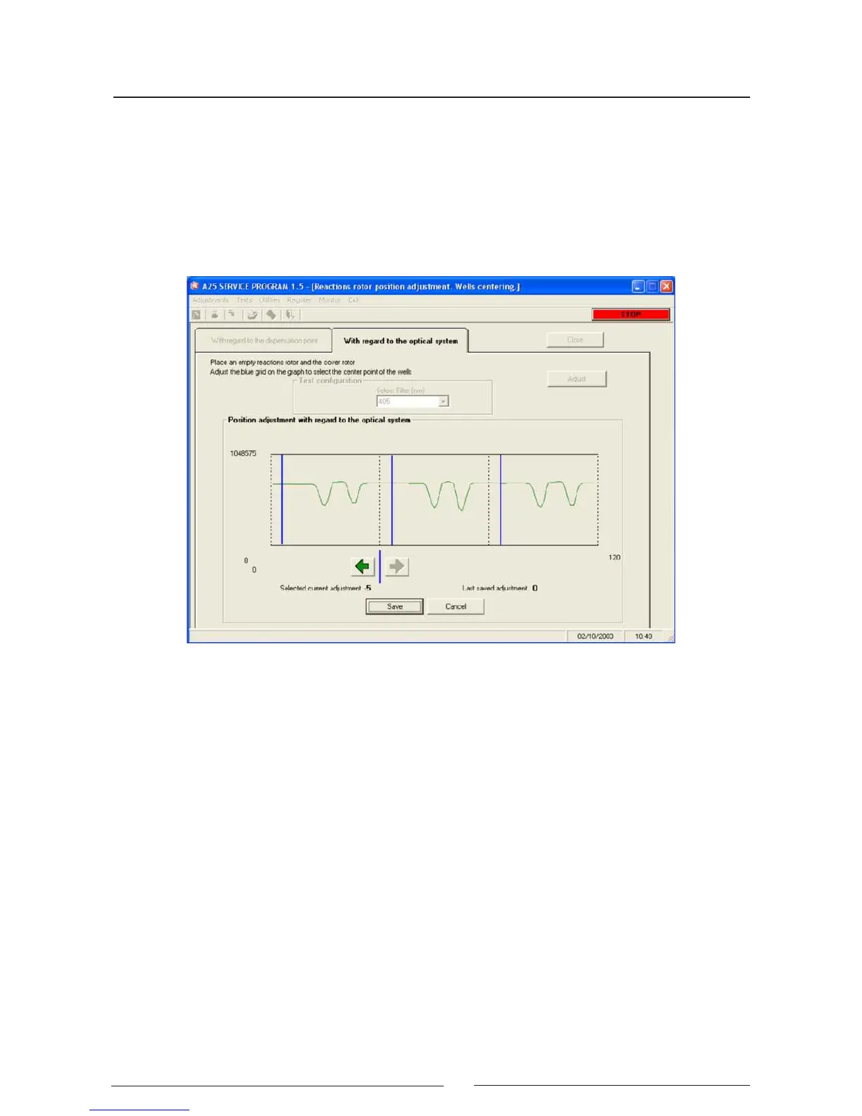
made through these wells at the wavelength selected by the technician. Once the readings have ended, the
program shows a graph of the light intensity measured on the rotor steps. On this graph, the program indica-
tes at which points the optical readings are made on each of the 3 wells when the analysis is made, with the
coordinate of the reading point of the rst well currently programd in the analyzer. If necessary, the technician
can move the reading points over the graph jointly using two buttons. The optimum reading point is that which
globally maximises the light intensity for the three wells. At all times, the screen shows the current coordinate
of the reading in the rst well and the last coordinate stored, as additional information for the technician. When
the position is satisfactory, the current coordinate of the reading point of the rst well can be stored by pressing
the Store button. Pressing the Cancel button keeps the last stored value and the current value is not stored.
4.2.5 . Adjustment of the positioning of the lter wheel
This adjustment must be made with the rotor cover in position. The analyzer initialises the rotor and the lter
wheel and lls the rst rotor well with distilled water. Next, it takes optical readings through this well, turning the
lter wheel step by step, with a certain integration time as indicated by the technician (the concept of integration
time is explained in the section on photometric adjustments). Once the readings have ended, the program shows
a graph of the light intensity measured on the steps of the lter wheel. On this graph, the program indicates at
which points each of the lters is positioned when optical readings are taken when the analysis is carried out,
with the coordinate of the positioning of the lter 0 currently programd in the analyzer. If necessary, the technician
can move the reading points over the graph jointly using two buttons. The optimum reading point is that which
globally maximises the light intensity for all the lters. At all times, the screen shows the current coordinate
of the lter 0 and the last coordinate stored, as additional information for the technician. When the position is
satisfactory, the current coordinate of the positioning of the lter 0 can be stored by pressing the Store button.
Pressing the Cancel button keeps the last stored value and the current value is not stored.