33
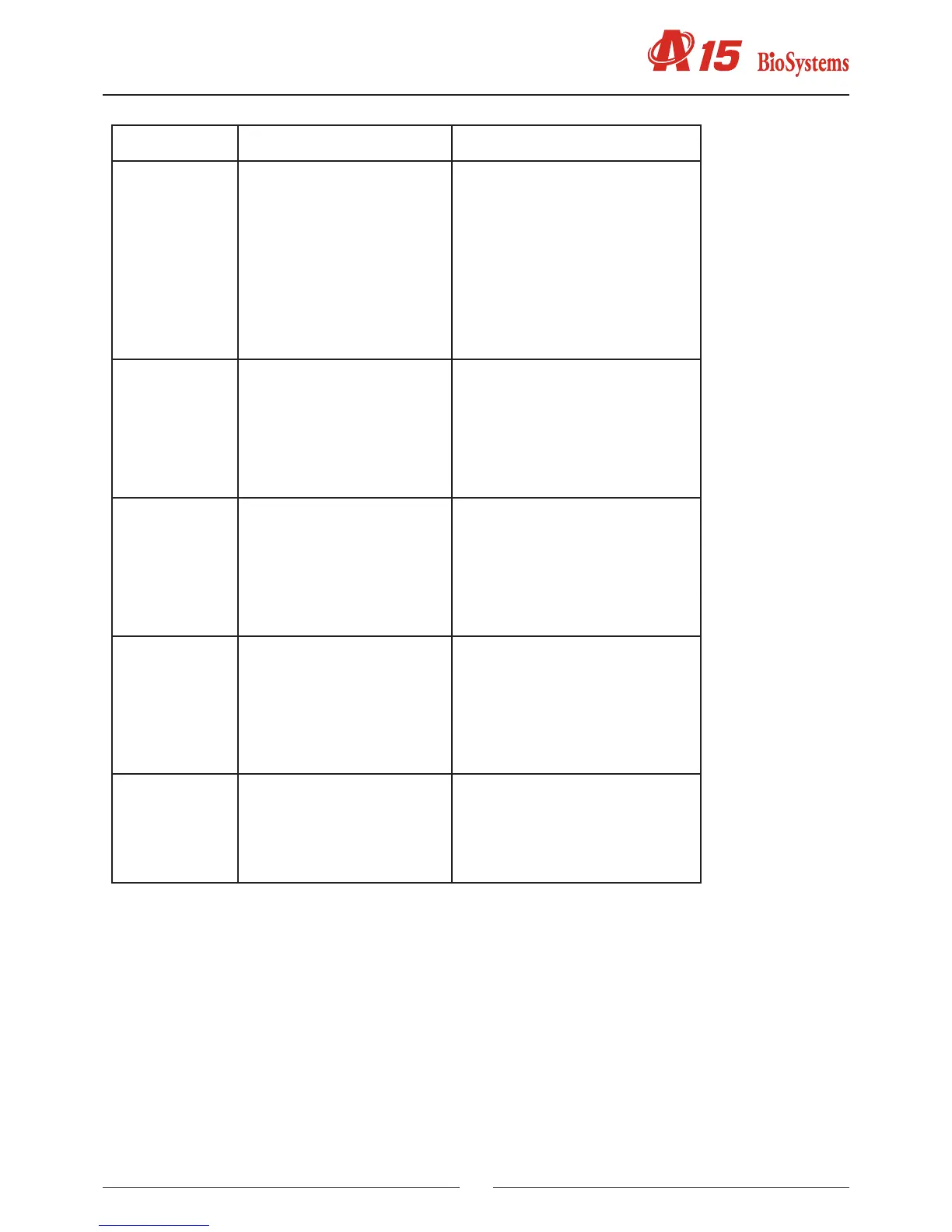
Connector Function Pins
J7 Connection to rotor intercon-
nection board (motor and
Peltier signals)
1 - coil 2 motor lters
2 - coil 2 motor lters
3 - coil 1 motor lters
4 - coil 1 rotor motor
5 - coil 1 motor lters
6 - coil 1 rotor motor
7 - Peltier
8 - coil 2 rotor motor
9 - Peltier
10 - coil 2 rotor motor
11 - V(24 V)
12 - Peltier fans
J8 Connection to interconnec-
tion board uids (electrically
operated valve and pump
signals)
1 - V(24 V)
2 - Waste pump
3 - V(24 V)
4 - Electrically operated valve
5 - coil 1 ceramic pump
6 - coil 1 ceramic pump
7 - coil 2 ceramic pump
8 - coil 2 ceramic pump
J9 Connection to interconnec-
tion board uids (ceramic
pump home and level sensor
signals)
1 - Waste bottle sensor input
2 - System liquid sensor input
3 - Bottle detection signal
4 - Rack level detection signal
5 - Ceramic pump home
6 - V DC
7 - GND
8 - Instrument cover detection
J10 Connection to needle board 1 - V (12 V)
2 - GND
3 - Home motor Z
4 - Needle thermistor
5 - Rack level detection signal
6 - V (24 V)
7 - Needle thermostat elements
8 - NC
J11 Connection to supply board 1 - V (12 V)
2 - GND
3 - V (24 V)
4 - V DC
5 - Fan control
6 - Lamp control