1 689 975 233 2018-05-08| Robert Bosch GmbH
20 | EPS 708 | Repairen
With software version 3.84 or lower and with label
from date of manufacture 2014-12 (see Fig. 30)
i The calibration values "ZME" and "ZME'" printed on
the label must not be interchanged. The calibration
value "ZME" must not be used for software version
3.84 or lower.
1. Enter the calibration values in the software as fol-
lows:
Calibration value on the label Input box in EP945 software
ZME' offset ZME / DRV
EAV offset EAV
2. Continue with <F4>.
3. Confirm the dialog with <F4> and continue with <F12>.
The calibration values are saved and the calibrati-
on date is displayed at the top right.
4. Continue with <F12>.
5. Back with <F11>.
" This completes the calibration.
With software version 4.35 or higher and with label
up to date of manufacture 2014-11 (see Fig. 29)
1. Enter the calibration values in the software as fol-
lows:
Calibration value on the label Input box in EP945 software
ZME offset ZME' / DRV'
EAV offset EAV
2. Continue with <F4>.
3. Confirm the dialog with <F4> and continue with <F12>.
The calibration values are saved and the calibrati-
on date is displayed at the top right.
4. Continue with <F12>.
5. Back with <F11>.
" This completes the calibration.
With software version 4.35 or higher and with label
from date of manufacture 2014-12 (see Fig. 30)
1. Enter the calibration values in the software as fol-
lows:
Calibration value on the label Input box in EP945 software
ZME offset ZME / DRV
ZME' offset ZME' / DRV'
EAV offset EAV
2. Continue with <F4>.
3. Confirm the dialog with <F4> and continue with <F12>.
The calibration values are saved and the calibrati-
on date is displayed at the top right.
4. Continue with <F12>.
5. Back with <F11>.
" This completes the calibration.
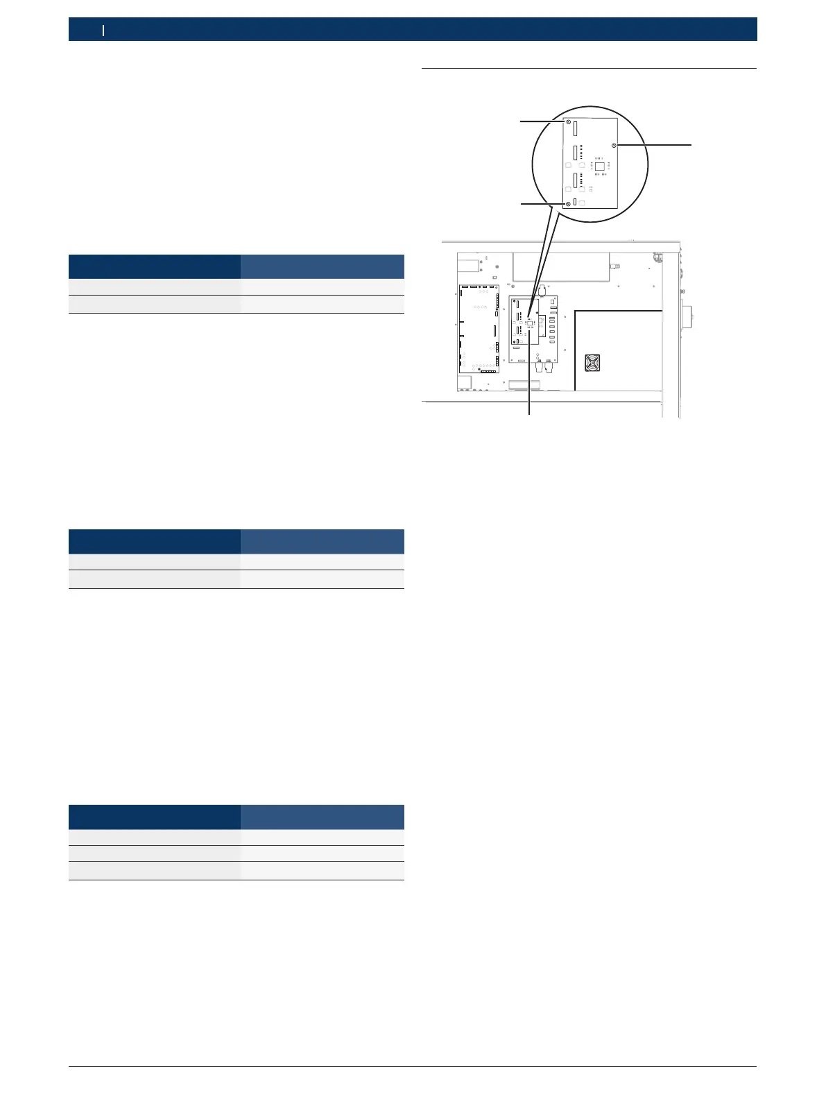
6.2 Replacing PCB (A6)
458863-07_Ri
1
3
2
Fig. 31: Replacing PCB 1 688 400 480 (A6)
6.2.1 Removing the PCB
1. Turn off the EPS 708 at the master switch.
2. Secure the master switch so that it cannot be
switched back on.
3. Unplug the mains plug or disconnect from mains
electricity.
4. Check that there is no power.
5. Remove the cover of the electronics compartment
! Pay attention to the plug locks when disconnecting
and connecting cables. Lack of care may result in
damage to connecting cables and plugs.
6. Disconnect all connecting cables from the PCB (A6)
(see Fig. 31, item 4).
7. Slacken Torx screws (items 1, 2 and 3).
8. Remove PCB (A6)
6.2.2 Installing the PCB
! Note the correct pin assignment when fitting the
new PCB (see circuit diagram 1 689 911 487 on
page 8).
¶ Install the new PCB in the reverse order.