1 689 975 233 2018-05-08| Robert Bosch GmbH
Calibrating the high-pressure rail | EPS 708 | 89 en
10.1.9 Checking measured values
1. Open the "Measurement functions" menu with
<F7>.
2. Select the "Automatic On/Off" menu item and acti-
vate the automatic function with <F12>.
The automatic symbol flashes in the operating
status display.
The system reaches the set values and the wai-
ting/measurement time commences. After the
waiting/measuring time has elapsed, the system
software automatically changes to the next test
step.
3. In the event of the message "System stop! No
further test steps available! Results
with F12 >> ", press <F12> to open the log.
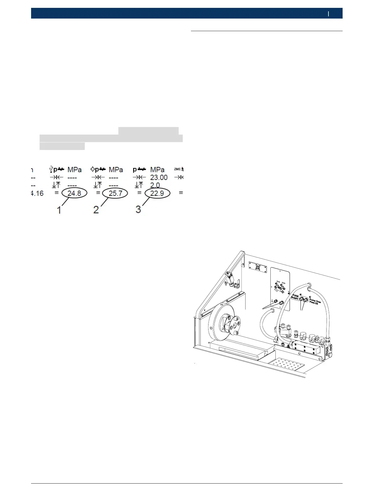
Fig. 156: Excerpt from the test log
1 Measured value for External pressure value
2 Measured value for Test bench pressure value upstream of filter
3 Measured value for Test bench pressure value.
4. At all verification points, compare the measured
values Test bench pressure value and Test bench
pressure value upstream of filter with External
pressure value (see Fig. 156). The difference in
pressure must not exceed 0.5MPa.
Calibration must be repeated if the pressure diffe-
rence is > 0.5 MPa.
10.1.10 Ending calibration
1. Exit the "Result printout" dialog box by pressing <Esc>.
2. In the "Injection component test main menu" start
screen, select <F7>.
You are asked to enter a password.
3. Enter the password in the input line: 1958
4. Confirm your entry with <F12>.
5. Select the Calibration >> Rail pressure sensor
menu option.
6. Select <F6> "Calib. check".
7. Continue with <F12>.
8. Exit the menu with <Esc>.
The system software reinitializes the devices.
9. Remove the USB connecting cable of the pressure
sensor from the PC.
10. Remove the pressure sensor from the high-pressure
rail.
11. Use a dummy plug to seal the connection for the
CRI846 distributor rail on the high-pressure rail.
12. Remove the common rail pump.
" Pressure sensor calibration is complete.
10.2 Performing the zero point adjust-
ment of pressure sensors
i After pressure sensors B1, B4, B5, B6 and B19 have
been replaced (only with lubricating-oil supply unit)
in the low-pressure circuit, a zero point adjustment
must be performed. For this, the pressure sensors
must be exposed to ambient pressure. All pressure
sensors are adjusted simultaneously.
1. Switch on the EPS 708 at the master switch.
2. Start the software EPS945.
The software performs initialization
3. In the "Injection component test main menu" start
screen, select <F7>.
A password request appears.
4. Enter the password in the input line: 1958
5. Confirm your entry with <F12>.
6. Select menu item "Calibration >> EPS708".
7. Continue with <F12>.
8. In the test area of EPS 708, remove the hose assem-
blies from both test oil connections
(Fig. 157, item1). The test connections
(Fig. 157, item 1) must be open.
9. Remove the hose assemblies from both lubricating
oil connections (Fig. 157, item 2). The lubricating oil
connections (Fig. 157, item 2) must be open.
X22
1
2
Fig. 157: EPS 708 Test area
10. Press <F2>.
11. Confirm query with <F4> and accept selection with
<F12>.
All print values are reset to zero.
12. Exit the window by pressing Esc.
13. Exit the configuration menu by pressing Esc twice.