1 689 975 233 2018-05-08| Robert Bosch GmbH
Repair | EPS 708 | 39 en
6.12 Replacing pressure switch (PV1) for
the fan in the water chiller
6.12.1 Disconnecting the pressure switch electri-
cally
1. Switch off the EPS 708 at the main switch.
2. Secure the main switch so that it cannot be swit-
ched back on.
3. Unplug the mains plug or disconnect from mains
electricity.
4. Check that there is no power.
5. Remove the front cover of the test oil area.
6. Remove the side cover of the test oil area.
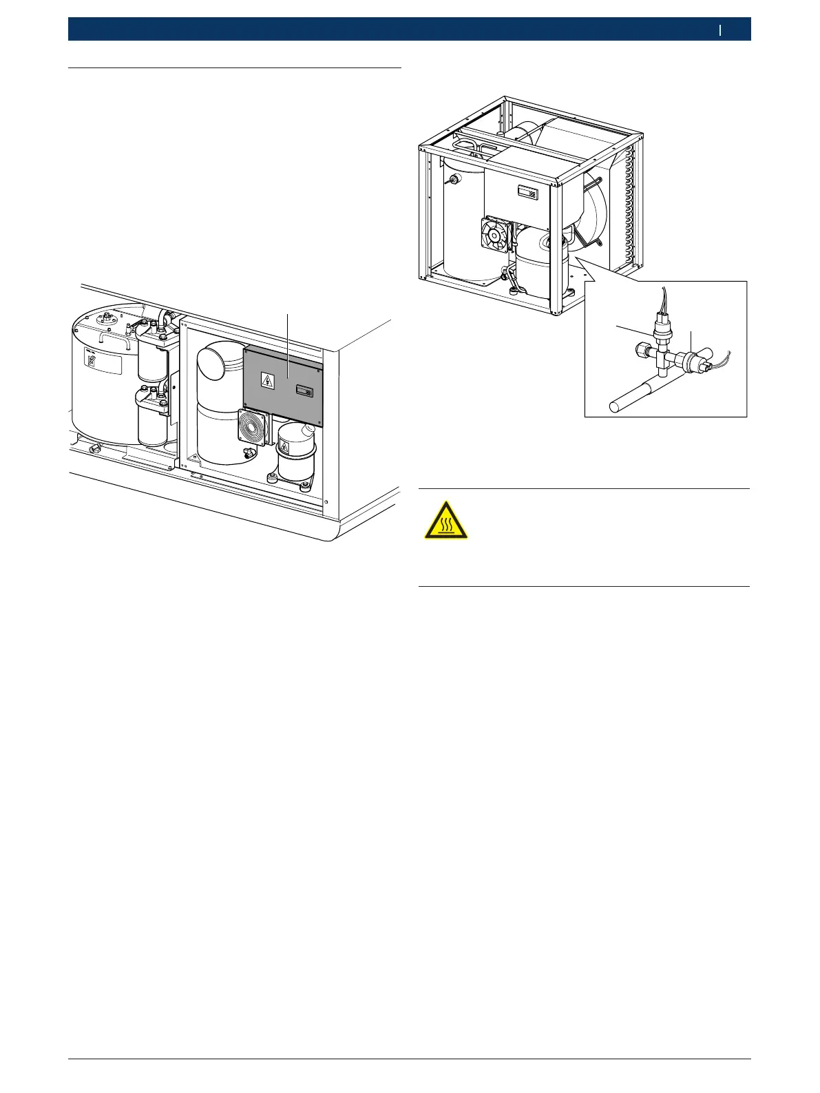
1
Fig. 62: Water chiller electrical cabinet
7. Remove the 4 fastening screws of the cover
(see Fig. 62, item 1).
8. Remove cover and place it to the side.
i For an overview of the electrical cabinet compo-
nents, see section 4.8.
9. In the electrical cabinet, remove all covers from all
cable ducts.
10. On terminal block X1 (see Fig. 18, item 6), loosen
terminal 11 and terminal 13, and remove the two
wires of the pressure switch connection cable.
11. Remove all cable ties.
12. Open the cable gland (see Fig. 15, item 5).
13. Pull the pressure switch connection cable out of the
electrical cabinet.
6.12.2 Removing the pressure switch
1
2
Fig. 63: Overview of pressure switch
1 Safety pressure switch HP1
2 Pressure switch PV1 for the fan
WARNING – Danger of frostbite from refri-
gerant!
Refrigerant causes severe frostbite on the skin
¶ Wear safety goggles
¶ Wear protective gloves.
! The pressure switch is screwed onto a connection
with an integrated Schrader valve. The Schrader val-
ve ensures that no refrigerant can escape from the
system when the pressure switch has been removed.
Nevertheless, a small amount of refrigerant may
escape when the pressure valve is being installed
or removed. Excessive refrigerant loss results in
reduced performance or a malfunction of the water
chiller.