1 689 975 233 2018-05-08| Robert Bosch GmbH
40 | EPS 708 | Repairen
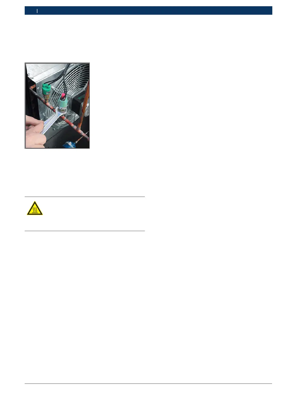
! When loosening the union nut on the safety pressure
switch, it is necessary to hold the pressure switch
firmly with a second wrench (see Fig. 64). Otherwi-
se, there is a risk that the connection can be broken
off.
Fig. 64: Installing the pressure switch
¶ Loosen the union nut on the pressure switch
(see Fig. 63, item 2) and remove the pressure
switch.
6.12.3 Installing the pressure switch
WARNING – Danger of frostbite from refri-
gerant!
Refrigerant causes severe frostbite on the skin
¶ Wear safety goggles
¶ Wear protective gloves.
! The pressure switch is screwed onto a connection
with an integrated Schrader valve. The Schrader val-
ve ensures that no refrigerant can escape from the
system when the pressure switch has been removed.
Nevertheless, a small amount of refrigerant may
escape when the pressure valve is being installed
or removed. Excessive refrigerant loss results in
reduced performance or a malfunction of the water
chiller.
! When tightening the union nut on the safety pressu-
re switch, it is necessary to hold the pressure switch
firmly with a second wrench. Otherwise, there is a
risk that the connection can be broken off (see Fig.
64).
i After the pressure switch has been installed, the
connection must be checked for leaks with a leak
detection spray. Have the leak detection spray ready
prior to installation.
1. Screw the pressure switch onto the connection.
2. Carefully tighten the union nut while holding the
connection securely with a second wrench.
3. Check the connection for leaks with the leak detec-
tion spray.
6.12.4 Connecting the pressure switch electrically
1. Push the connection cable into the electrical cabinet
through the cable gland (see Fig. 15, item 5).
i For an overview of the electrical cabinet compo-
nents, see section 4.8.
2. Attach the wires of the connection cable to terminal
11 and terminal 13 on terminal block X1
(see Fig. 18, item 6).
3. Place the connection cable in the cable duct.
4. Attach the covers to the cable ducts.
5. Tighten the cable gland (see Fig. 15, item 5).
6. Place the cover on the electrical cabinet and secure
with 4 fastening screws.
7. Secure the connection cable with cable ties.
6.12.5 Concluding operations
1. Check the protective conductor in accordance with
DGUV A3.
2. Switch on EPS 708.
3. Run the functional test (see section 6.7.6). During
the function test, occasionally check the safety
switch connection for leaks with the leak detection
spray.
4. After a successful function test, reattach all covers.
5. Attach the side cover of the test oil area.
6. Attach the front cover of the test oil area.