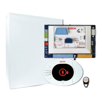
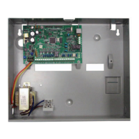
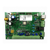
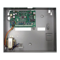
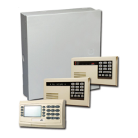
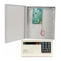
Figure 2.1: Overview of the System Component Location for the ICP-EZM2-EU Enclosure
Callouts - Description
1 Port for ICP-EZRU-V3 ROM Update Key and Programming Key
2 Enclosure Cover and Wall Tamper Switch
3 Ground connection
Connect ground wire from enclosure to enclosure door.
4 Module mounting location
5 Module mounting location
6 System test button
When the system is completely installed and programmed, press the system test button to start a full
system test.
7 Port for ICP-EZVM voice module
20 en | Overview Easy Series Control Panel
2014.09 | 01 | F.01U.306.221 System Reference Guide Bosch Security Systems, Inc.
 Loading...
