Service
6-6 P/N M/97-520
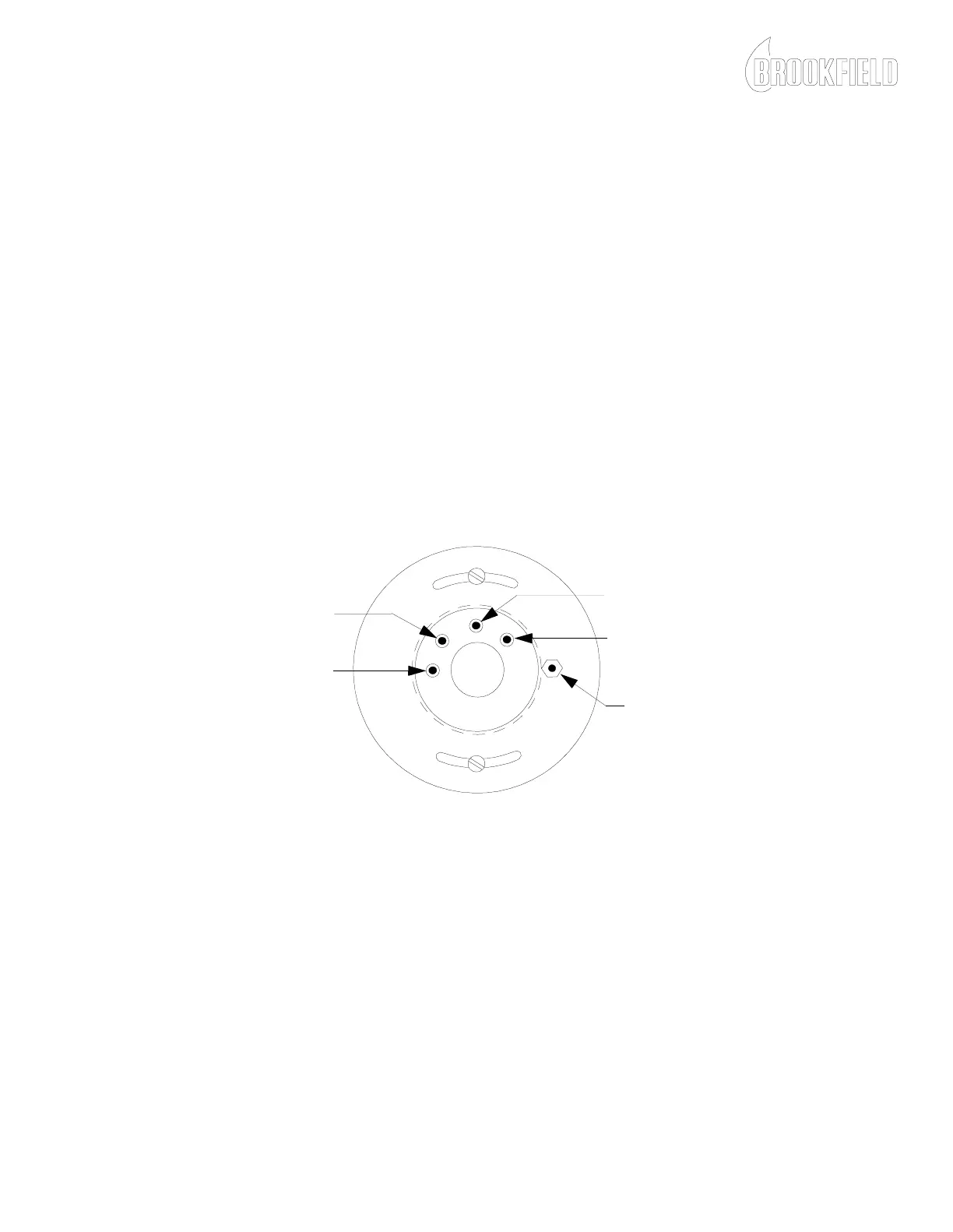
8. Refer to Figure 6-3 and perform an electrical test on the Microsyn
field coil as follows:
a. Set the DVM to measure resistance (Ω).
b. Connect the positive lead of the DVM to Pin 1.
c. Connect the negative lead of the DVM to Pin 2.
d. The DVM should indicate 2.0 ± 1 Ω.
e. Connect the positive lead of the DVM to Pin 3.
f. Connect the negative lead of the DVM to Pin 4.
g. The DVM should indicate 1500 ± 500 Ω.
h. If the measured values correspond with the specifications in
steps d and g, then proceed with step 9. If the measured
values do not correspond with the specifications in steps d
and g, then the Microsyn field coil must be replaced. Refer
to Microsyn Field Coil Replacement within this section.
Figure 6-3: Microsyn Field Coil Pin Identification
9. Refer to Figure 6-4 and remove the armature assembly as follows:
a. Using the Brookfield Engineering Laboratories, Inc.
armature wrench P/N TT100-1T, hold the armature in place.
b. Using a 9/32 inch wrench, loosen the armature clamping
nut and remove the armature assembly.
PIN # 1 (GREEN WIRE)
PIN # 2 (RED WIRE)
PIN # 3 (BLUE WIRE)
PIN # 4 (YELLOW WIRE)
GROUND STUD
(PURPLE WIRE)