3-103
Confidential
(12)Release the wiring of the Maintenance unit.
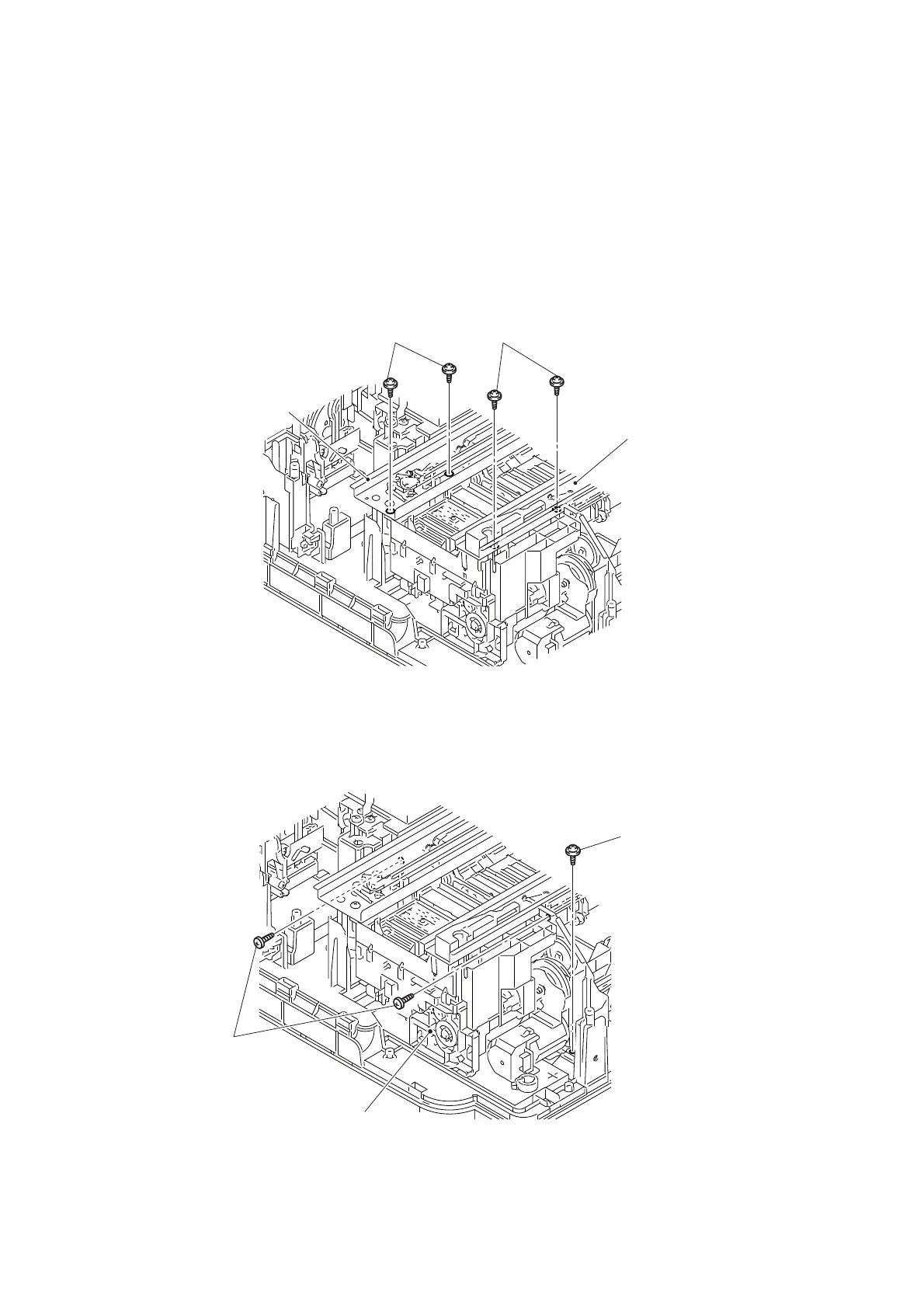
(13)Remove the two screws (TAPTITE CUP B M3x10) from the CR frame ASSY.
Assembling Note: When assembling the two screws (TAPTITE CUP B M3 x 10),
temporarily remove the screw in step (3) of “9.47 Carriage Motor”
first. Then, assemble the two screws in the order as shown in the
figure, and lastly reassemble the temporarily removed screw.
(14)Remove the two screws (TAPTITE CUP B M3x10) from the CR guide rail.
Assembling Note: When assembling the two screws (TAPTITE CUP B M3 x 10),
assemble them in the order as shown in the figure.
Fig. 3-123
(15)Remove the screw (<Made-in-China machine> TAPTITE CUP B M3x10, <Made-
in-Philippines machine> TAPTITE BIND B M4x12) and the two screws (SCREW
BIND M3x6) from the Maintenance unit.
Fig. 3-124
CR guide rail
CR frame ASSY
1
2
1
2
TAPTITE CUP B M3x10
TAPTITE CUP B M3x10
Maintenance unit
SCREW BIND M3x6
<Made-in-China machine>
TAPTITE CUP B M3x10
<Made-in-Philippines machine>
TAPTITE BIND B M4x12
 Loading...