114
SYSTEM ANALYSIS
ELECTRICAL CONNECTIONS
ELECTRICAL
CONNECTIONS
Inspect wiring and electrical connections. Disas-
semble and clean all corroded connections.
Replace damaged wiring, connectors, or termi-
nals. Repair any shorted electrical circuits. Refer
to wiring diagrams and reference charts to identify
specific wiring details.
IMPORTANT: The key to effective troubleshoot-
ing is confirming the proper operation of each
engine system. Causes of electrical failures may
be difficult to isolate. Check the integrity of all con-
nections, grounds, and wiring prior to replacing a
suspect component.
Inspect the condition and positioning of the follow-
ing components:
• Engine Management Module (EMM): wiring to
EMM connectors and pins
• Stator: connections to EMM, wiring to connec-
tors, and connector pins
• Engine wiring harness and connectors
Refer to AMP Connectors on p. 169 for AMP
connector servicing procedures.
Engine Harness to Stator Connector
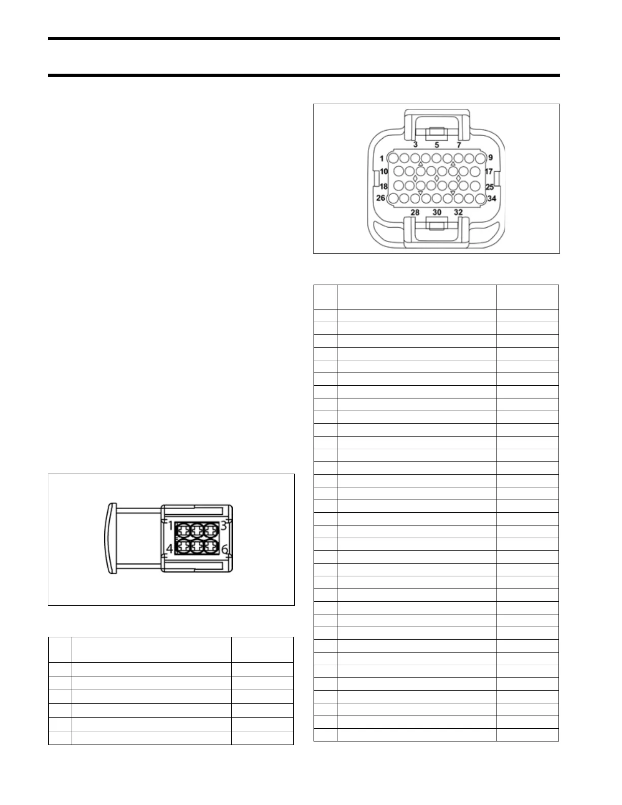
EMM J1-A Connector
004050
Pin
No.
Description of Circuit Wire Color
1 Stator winding (1S) Yellow
2 Stator winding (3S) Orange
3 Stator winding (2S) Brown
4 Stator winding (1F) Yellow /White
5 Stator winding (3F) Orange/White
6 Stator winding (2F) Brown/White
001875
Pin
No.
Description of Circuit Wire Color
1 Oil Pressure switch Tan/White
2 Diagnostic connector Red
3 Diagnostic connector White
4 Ground, water in fuel (digital) Black
5 Oil level switch Tan/Black
6 Crankshaft position sensor (CPS) Yellow
7 Ground, CPS (digital) White
8 Bootstrap connector (programming) Blk/Orange
9 Stop circuit Blk/Yellow
10 Throttle position sensor (TPS) 5 V Red
11 Ground (analog) Black
12 Engine temperature sensor, port Pink/Black
13 CANbus, NET-L Blue
14 CANbus, NET-H White
15 Water pressure Pink
16 Tachometer Gray
17 CHECK ENGINE signal, SystemCheck Tan/Orange
18 TPS Green
19 Engine temperature sensor, starboard Pink/Black
20 Air temperature sensor Pink/Blue
21 CANbus, NET-S Red
22 CANbus, NET-C Black
23 Water in fuel Pink/Green
24 NO OIL signal, SystemCheck Tan/Yellow
25 WATER TEMP signal, SystemCheck Tan
26 Start signal Yellow/Red
27 none N/A
28 none N/A
29 Shift switch (shift linkage) Black/Yellow
30 Trim relay, UP Blue/White
31 Trim relay, DOWN Green/White
32 Trim sender, IN White/Tan
33 Trim sender, OUT White/Tan
34 LOW OIL signal, SystemCheck Tan/Black