154
ELECTRICAL AND IGNITION
FLYWHEEL AND STATOR SERVICING
Installation
IMPORTANT: If a new EMM is being installed,
refer to EMM Transfer on p. 111.
Install J2 connector
Align slots in starboard side of EMM case with iso-
lator mounts on electrical harness base. Slide
EMM into position.
Install two EMM retaining screws. Tighten screws
12 to 16 in. lbs. (1.5 to 2 N·m).
Install J1-A and J1-B connectors.
Install exhaust pressure hose and cooling hoses.
Secure with tie straps.
FLYWHEEL AND STATOR
SERVICING
IMPORTANT: Weak flywheel magnets can
cause low ignition voltage and affect outboard per-
formance. Weak flywheel magnets can also cause
low readings on ignition test equipment such as
the peak-reading voltmeter, which might cause
unnecessary replacement of ignition components.
An accurate test of alternator output can help
determine the flywheel’s condition. Refer to
CHARGING SYSTEM TESTS on p. 142.
Flywheel Removal
Remove the EMM. Refer to EMM SERVICING on
p. 153.
Disconnect the vapor separator vent hose, crank-
shaft position sensor, throttle position sensor, air
temperature sensor, and oil pump electrical con-
nectors.
Disconnect the stator connector, two port side trim
system connectors, port engine temperature sen-
sor, and the port ground terminal.
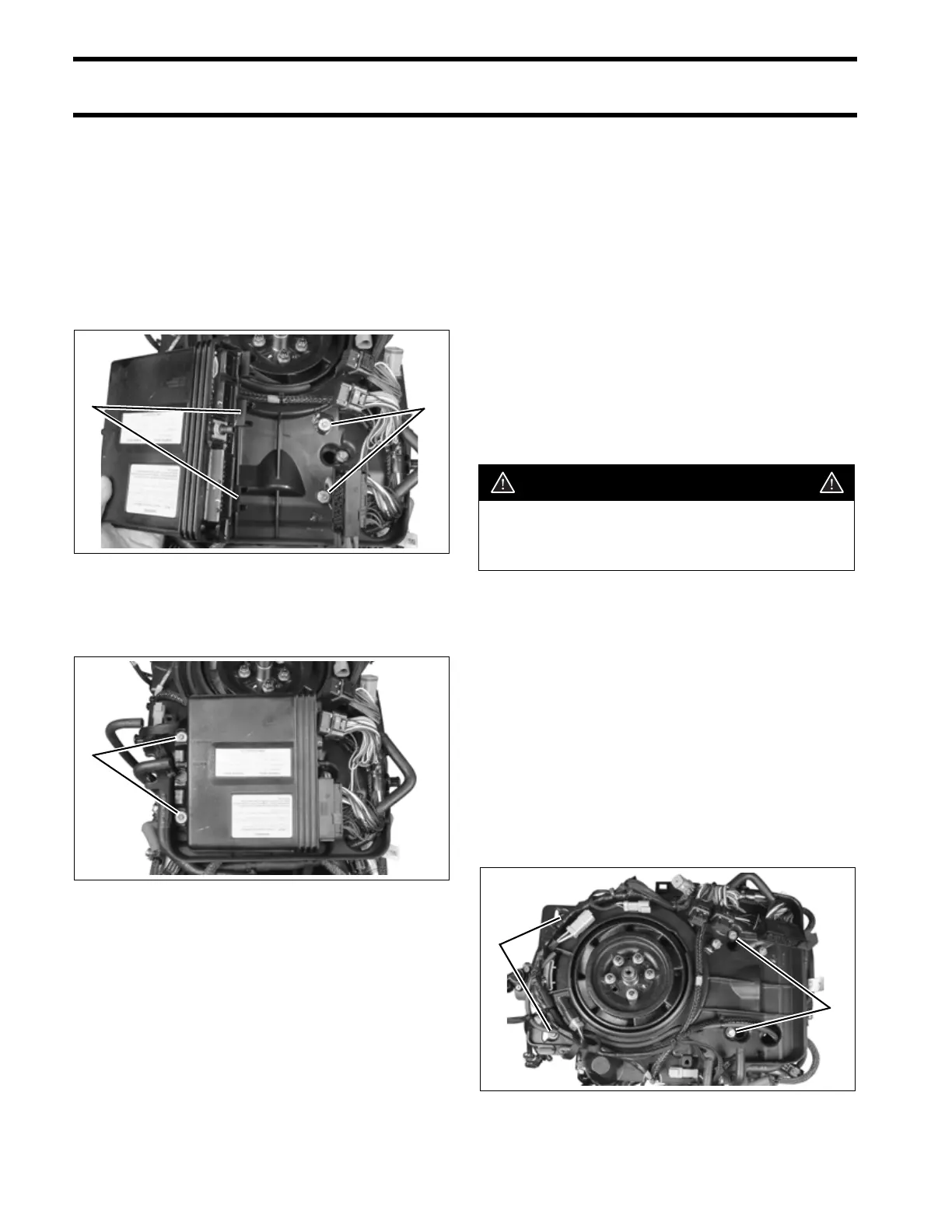
Remove the four screws holding the electrical har-
ness base.
1. EMM mounting slots
2. Isolator mounts
005377
1. EMM mounting screws 005375
21
1
WARNING
To prevent accidental starting while ser-
vicing, disconnect battery cables at the
battery.
1. Harness base screws 005378
1
1