129
SYSTEM ANALYSIS
IGNITION OUTPUT
5
Results:
• Spark control on all cylinders and outboard
runs, Refer to Running Ignition Tests on
p. 129 and Dynamic Tests on p. 120.
• NO spark control on one or more cylinders, note
cylinders. Refer to Ignition Primary Circuit
Resistance Test on p. 130 and IGNITION COIL
TESTS on p. 141.
Running Ignition Tests
The purpose of this test is to isolate ignition sys-
tem malfunction. This test should be used in con-
junction with other ignition system tests to identify
component failures. This test provides limited
information. Use the findings of this test to elimi-
nate ignition system components. A thorough
understanding of the outboard’s ignition system is
required.
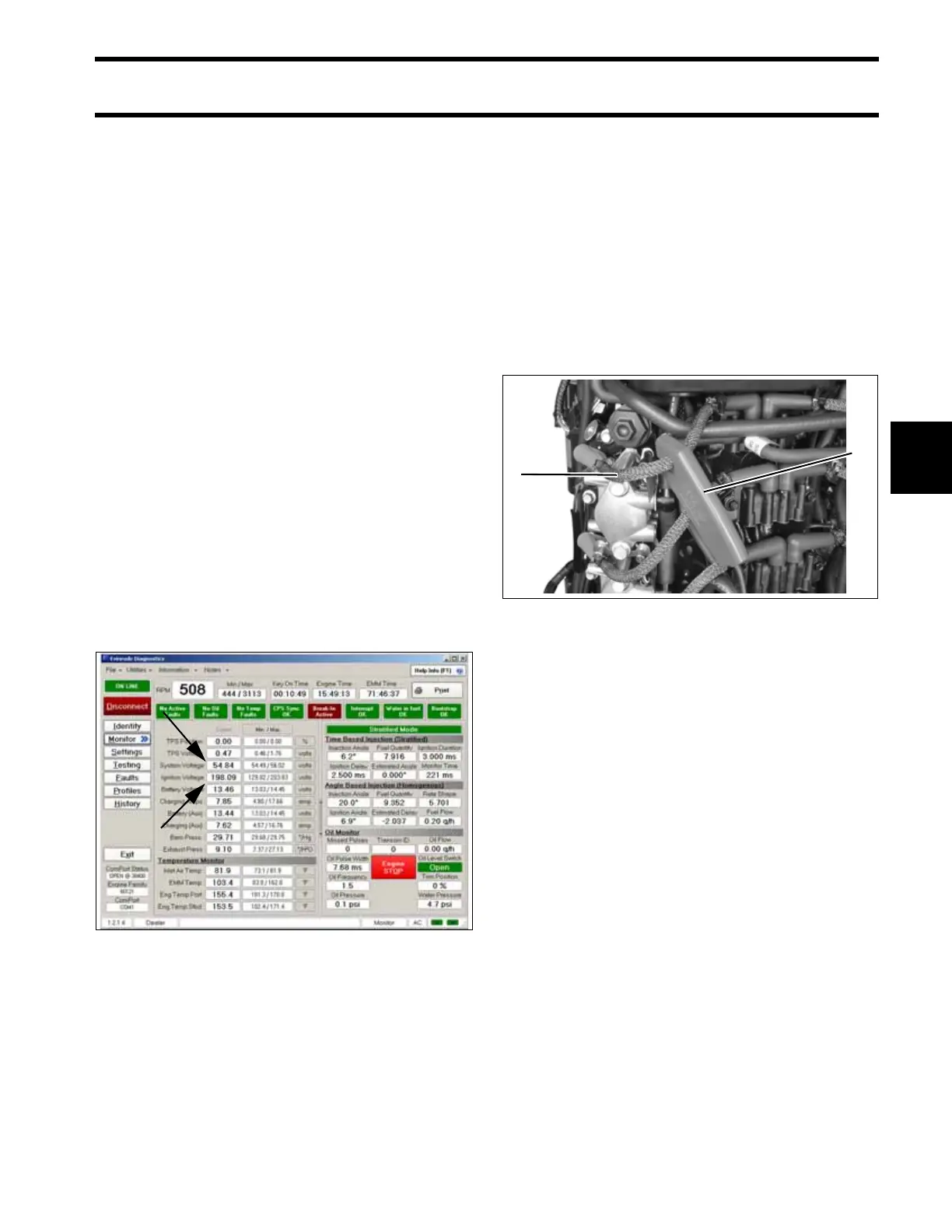
Monitor Voltage Outputs
Use the Evinrude Diagnostics Software program
to monitor system voltage (55 V) and ignition volt-
age (200 V).
• Voltage readings at a specific speed (RPM)
should be steady.
Results:
Low voltages: refer to System Voltage on p. 128
and Ignition Voltage on p. 127.
Monitor Ignition Output with Timing Light
Use a timing light to monitor the spark signal
through each of the high tension spark plug wires.
Start outboard and observe the timing light’s
strobe. Look for a consistent flash and only one
flash per revolution. The strobe of the timing light
should be consistent or the same for each cylin-
der’s ignition output.
IMPORTANT: Test on primary circuit if strobe
from secondary circuit appears faulty.
Results:
Steady voltage and strobe:
• Inspect or replace spark plugs, check fuel sys-
tem performance, and / or eliminate the possi-
bility of internal engine damage.
Voltages are steady, engine misfires:
• Check CPS air gap and resistance, check igni-
tion voltage while problem is occurring. See
Ignition Primary Circuit Resistance Test on
p. 130 and IGNITION COIL TESTS on p. 141.
Voltages fluctuate, engine misfires:
• Inspect condition of battery and connections,
test capacitor, and check all ground connec-
tions. See System Voltage on p. 128, Ignition
Voltage on p. 127, Ignition Primary Circuit
Resistance Test on p. 130 and IGNITION COIL
TESTS on p. 141.
IMPORTANT: If a running problem occurs at
about 1200 RPM, the outboard may be in S.A.F.E.
Refer to Conditions that initiate S.A.F.E. on
p. 103.
Engine Monitor Screen, System and Ignition Voltage 005141
1. Timing light pick-up
2. Secondary, high tension wire
005319
1
2