119
SYSTEM ANALYSIS
DIAGNOSTIC PROCEDURES
5
Symptoms
Outboard will not crank, starter does not
operate:
• Check condition of battery and cables (main
battery switch and cables). Make sure battery
cables are not reversed.
• Confirm that B+ is present at “A” terminal (pur-
ple wire) of starter solenoid with key switch in
the ON position.
• Proceed to START CIRCUIT on p. 122. Repair
starter or start circuit as needed.
Outboard cranks, will not start:
• Use LED indicators of EMM for initial diagnostic
information.
• Perform a spark test using the Evinrude Diag-
nostics Software program. Refer to IGNITION
OUTPUT on p. 127.
Results:
Steady spark on all cylinders and proper ignition
voltage:
• Check operation of all fuel injectors. Refer to
FUEL COMPONENT TESTS on p. 184.
• Check fuel quality and that fuel is present at
injectors.
• Refer to FUEL COMPONENT TESTS on p. 184
for fuel system pressure tests.
No spark on one or more cylinders:
• Note cylinder with no ignition output. Refer to
IGNITION OUTPUT on p. 127.
• Monitor cranking RPM using the diagnostic pro-
gram (approximately 175 RPM, minimum 75
RPM).
• Check CPS operation (verify RPM reading.)
• Perform ignition circuit resistance test(s). Refer
to Ignition Primary Circuit Resistance Test
on p. 130 and IGNITION COIL TESTS on
p. 141.
Outboard runs:
• Use Evinrude Diagnostics Software program to
perform Dynamic Tests. See Dynamic Tests on
p. 133.
• Use the engine Monitor screen of the Evinrude
Diagnostics Software program to observe circuit
voltages. Refer to Engine Monitoring Informa-
tion on p. 121.
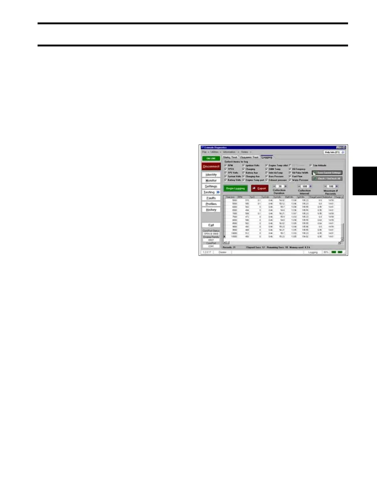
• Use the diagnostic software Logging function to
record engine data as a runability problem is
occurring.
• Use an inductive timing light to monitor the
injector circuits and ignition primary circuits.
Refer to Testing with Timing Light on p. 120,
IGNITION OUTPUT on p. 127, FUEL DELIV-
ERY on p. 131 and FUEL COMPONENT
TESTS on p. 184.
• Use an inductive amp meter to monitor injector
circuit current. Compare readings of all circuits
to identify possible failure.
Logging Screen 005154