43
INSTALLATION AND PREDELIVERY
BOAT RIGGING
2
Oiling System Set-Up
Location
IMPORTANT:
Consider the installation location
of the oil tank carefully. The oil tank is vented to
the atmosphere. To avoid serious powerhead
damage, be sure the oil tank is installed in a loca-
tion that does not allow constant exposure to sun-
light, rain, bilge water or spray.
Select a mounting location that provides:
• A solid place to mount the tank;
• A dry location that prevents exposure to rain or
spraying water;
• Access for adding oil;
• Access to oil-primer bulb; and
• Interference-free hose and wire routing to out-
board.
Each oil tank is originally fitted with a single oil
pickup assembly with 15 ft. (4.5 m) of oil supply
hose and 17 ft. (5.2 m) of sending unit wiring har-
ness.
If necessary, the oil tank can be mounted further
from the outboard than the supplied hoses and
harness allow. The maximum length of oil supply
hose that can be fitted to the oil tank is 25 ft.
(7.6 m).
IMPORTANT: Do not add hose to an existing oil
supply hose.
If the oil tank requires more than 15 ft. (4.5 m) of
oil supply hose:
• Oil supply hose between the primer bulb and
outboard must be replaced with one continuous
length of 1/4 in. (6.4 mm) hose.
• Maximum length of hose is 25 ft. (7.6 m).
• Replacement hose must be designated for fuel
or oil use and approved for marine use.
• Extend wiring harness with 16 gauge AWG
wire.
• Protect connections with heat shrink tube.
• Maintain wire color and polarity when extending
harness.
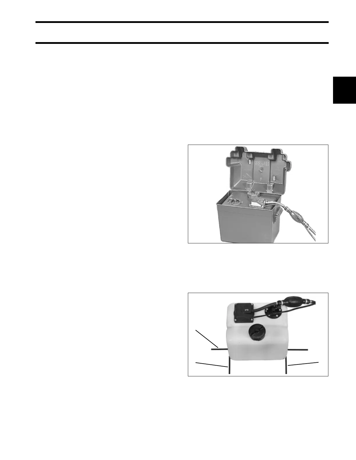
An appropriately sized battery box may be used to
conceal and protect the oil tank, if desired.
IMPORTANT: Be sure box includes drain holes
so it does not fill with water and contaminate oil.
Mounting
Place tank in selected position. Mark one line
under groove in tank bottom and lines at each end
of tank.
Make sure hole locations provide enough clear-
ance for fastening screws. Screws should not con-
tact or penetrate hull.
000074
1. Center line of oil tank
2. Ends of tank
44737
2
1
2