157
ELECTRICAL AND IGNITION
TIMING ADJUSTMENTS
6
Install the electrical harness base and secure with
four screws. Torque screws to 60 to 84 in. lbs (7 to
9.5 N·m).
Reconnect the stator connector, two port side trim
system connectors, port engine temperature sen-
sor, and the port ground terminal.
Reconnect the crankshaft position sensor, throttle
position sensor, air temperature sensor, and oil
pump electrical connectors.
Install the EMM. Refer to EMM SERVICING on
p. 153.
IMPORTANT: Perform the timing verification
procedure after flywheel removal or replacement.
Refer to TIMING ADJUSTMENTS on p. 157.
TIMING ADJUSTMENTS
Timing Pointer
The timing pointer must be adjusted to indicate
“top dead center” (TDC) of the number 1 piston.
This reference to the position of the number 1 pis-
ton is used to synchronize the electronic timing
controlled by the EMM with the mechanical posi-
tion of the number 1 piston. Use the Evinrude
Diagnostics Software program to verify and adjust
timing. Refer to the software’s “Help Info” for out-
board timing verification procedures.
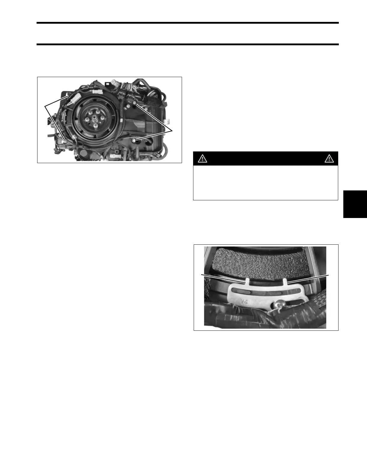
IMPORTANT: The pointer on these models has
two indicator points. The point labeled “V4” is
used for 60° V4 models. The unlabeled point is
used for 60° V6 models.
Turn the key switch OFF and disconnect the bat-
tery cables at the battery.
Remove spark plugs.
1. Harness base screws 005378
1
1
WARNING
To prevent accidental starting while ser-
vicing, remove emergency stop lanyard
and disconnect the battery cables at the
battery.
1. V4 pointer
2. V6 pointer
005385
21