123
SYSTEM ANALYSIS
START CIRCUIT
5
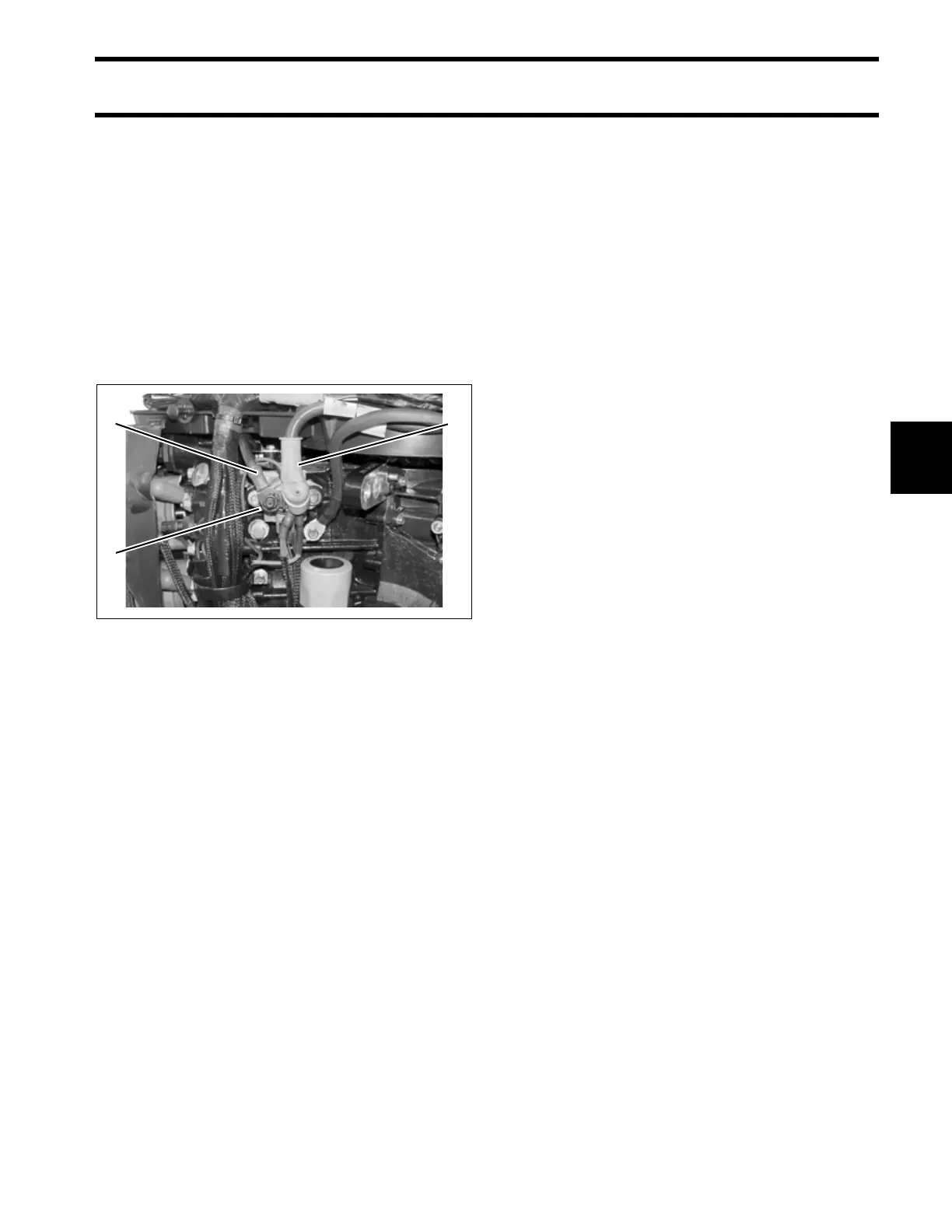
Starter Solenoid
• Starter solenoid and connections
• Starter solenoid switched ground (NEG), termi-
nal “B”
• Starter cable (solenoid to starter motor)
• 12 V from solenoid terminal (POS) and engine
harness (red wire) to 10 A fuse
Starter Motor and Drive Gear
•
Starter motor operation, refer to ELECTRIC
STARTER SERVICING on p. 161.
• Starter bendix operation.
Starter Solenoid Activation
Solenoid Wiring
The positive (B+) battery cable connects to the
large lower terminal of the starter solenoid. This
terminal also provides the 12 V power supply to
the engine harness (red wire) and the 10 A fuse.
The red/purple wire from the fuse holder (10 A)
provides 12 V to terminal “B” of key switch. The
negative (B–) battery cable connects to the main
ground stud located next to starter solenoid.
Engine Wire Harness
Contains the following circuits:
• Red/purple output wire from fuse and provides
12 V to instrument harness
• Purple wire provides switched 12 V to solenoid
(terminal “A”) and EMM
• Yellow/red wire provides switched 12 V to EMM
• Brown/white wire from terminal 11 of EMM J1-B
connector provides switched ground (NEG) to
starter solenoid (terminal “B”)
Instrument Wire Harness
Contains the following circuits:
• Red/purple wire provides 12 V to key switch ter-
minal “B”
• Purple wire provides switched 12 V to engine
wire harness
• Yellow/red wire from terminal “S” of key switch
provides switched 12 V to EMM (key switch in
START position)
Key Switch
Terminal “B” of key switch receives 12 V input
from 10 A fuse.
IMPORTANT: Repeat failures of fuse could be
the result of faulty connections or accessories.
The 12 V accessory circuit (purple wire from ter-
minal “A” of key switch) is often used to power
gauges.
1. Starter solenoid
2. Starter cable
3. POS battery cable
005320
32
1