292
MIDSECTION
EXHAUST HOUSING
V4 MODELS
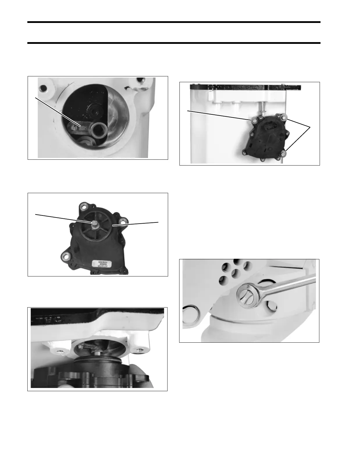
Check that exhaust valve linkage is oriented as
shown. “OUT” marking on lever must be visible.
Apply a small amount of Triple-Guard grease to
the actuator shaft and o-ring.
Carefully engage actuator shaft in linkage lever.
Rotate and push actuator into position. Apply Tri-
ple-Guard grease to screw threads and install
screws and washers. Tighten screws to 60 to 84
in. lbs. (7 to 9.5 N·m).
IMPORTANT: Fill actuator electrical connec-
tors with Electrical Grease before installation.
Installation
Bring the exhaust housing into position with the
stern bracket.
Install four new lower mount screws. These
screws have lock-patch pre-applied. Torque
screws to 38 to 45 ft. lbs. (52 to 61 N·m).
Install powerhead. Refer to Powerhead INSTAL-
LATION on p. 262.
Install gearcase. Refer to Gearcase REMOVAL
AND INSTALLATION on p. 308.
1. “OUT” mark 005208
1. Shaft
2. O-ring
005209
005219
1
2
1
1. Actuator screws 005206
23036
1
1