127
SYSTEM ANALYSIS
IGNITION OUTPUT
5
IGNITION OUTPUT
Wiring Inspection
Visually inspect all wiring, connections, and
grounds. Use an ohmmeter and perform resis-
tance tests on all ground circuits and connections.
Ohmmeter readings should be approximately
0.0 Ω.
Check that all engine wire harness grounds have
continuity to the cylinder/crankcase.
Make sure battery is fully charged.
Clean or repair all ground circuits, wiring, and con-
nections as needed. Refer to ELECTRICAL CON-
NECTIONS on p. 114.
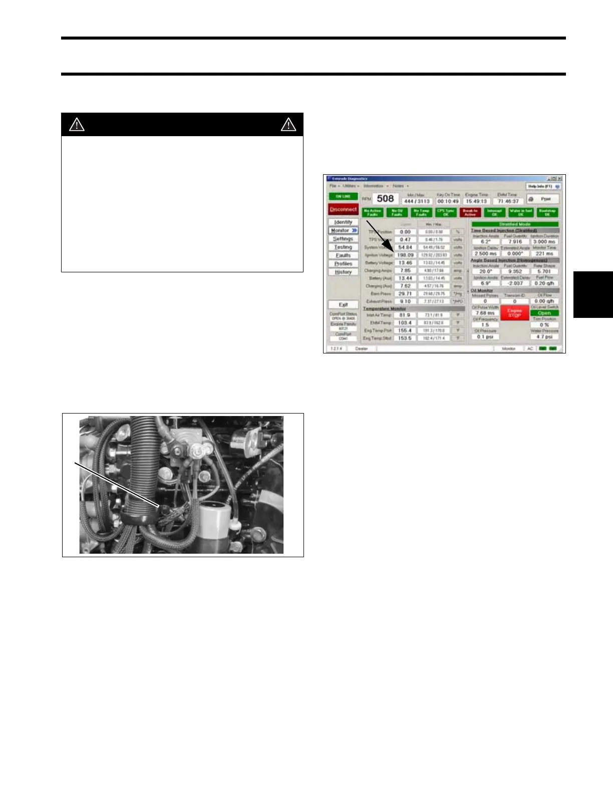
Ignition Voltage
Use the Evinrude Diagnostics Software program
to check ignition voltage to the primary ignition cir-
cuit(s). Check the EMM’s ignition voltage to the
primary circuits of the ignition coils on the engine
Monitor screen.
Results:
• “KEY ON” - 125 V ± 10, Ignition voltage is
GOOD, check voltage with outboard “running”.
Refer to Static Spark Test on p. 128.
• “KEY ON” - less than 125 V ± 10, check system
voltage to EMM. Refer to System Voltage on
p. 128. Note: Key ON voltage will not be con-
stant (fluctuates 125 - 200 V range)
• “RUNNING” - 200 V ± 10, Ignition voltage is
GOOD. Refer to Static Spark Test on p. 128
• “RUNNING” - less than 200 V ± 10, check stator
output to EMM. Refer to System Voltage on
p. 128 and STATOR TESTS on p. 141
Low or no voltage on EMM ignition circuit:
• Check system voltage (55 V) input to ignition
circuit on pin 4 of EMM J1-B connector.
DANGER
The electrical system presents a serious
shock hazard. Allow outboard to sit for
two minutes after running before handling
capacitor or 55 V electrical components.
Failure to handle capacitor properly can
result in uncontrolled electrical discharge
and possible electrical shock to humans.
DO NOT handle primary or secondary igni-
tion components while outboard is run-
ning or flywheel is turning.
1. Main engine harness ground 005315
1
Engine Monitor Screen, Ignition Voltage 005141