152
ELECTRICAL AND IGNITION
EXHAUST VALVE RELAY TESTS
Test Procedure
Make sure red and black wires are connected to
12 V battery power supply.
Set voltmeter to 12 VDC scale. Connect test leads
to terminals “A” and “B” of TNT motor connector.
Use a wire jumper to alternately connect B+ to ter-
minals “1” and “2” of tilt and trim switch connector.
The meter must indicate battery voltage (12 V)
with B+ connected to either terminal.
EXHAUST VALVE RELAY
TESTS
The exhaust valve control module contains the cir-
cuitry and relays required to operate the exhaust
valve actuator.
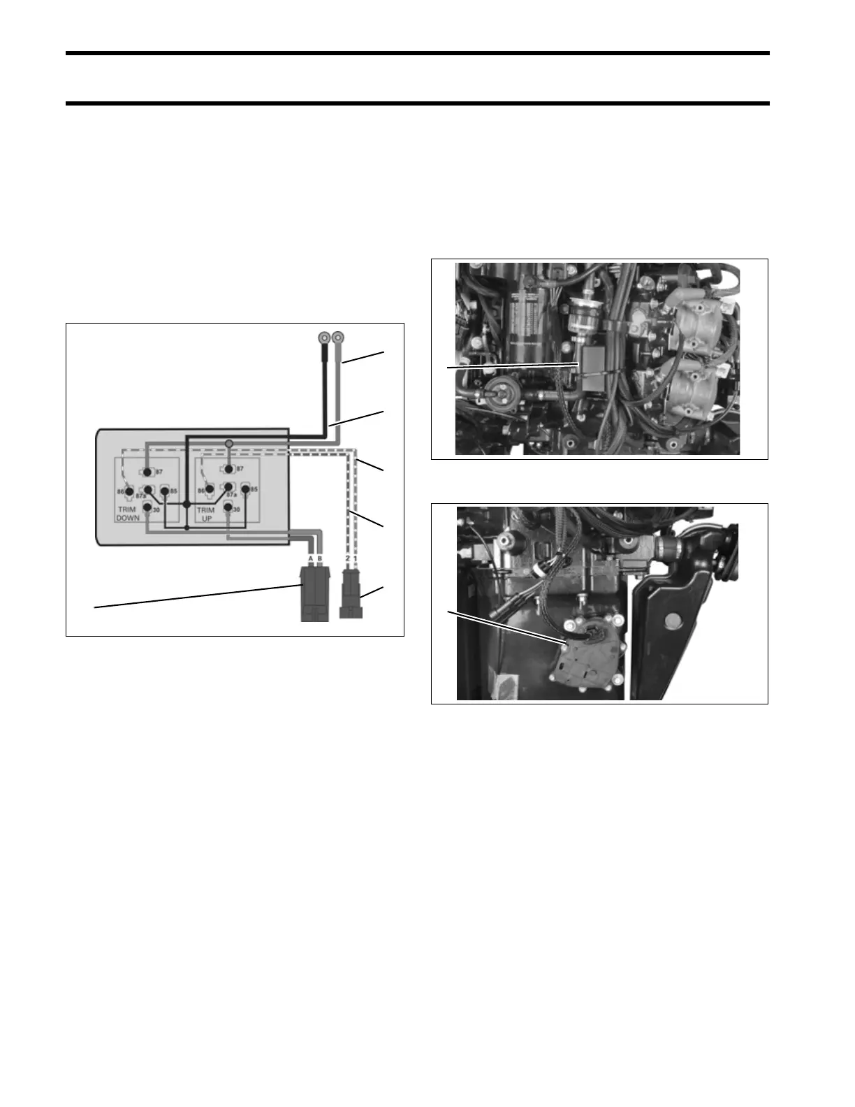
Tilt and Trim Module Diagram
1. Green/white wire
2. Blue/white wire
3. B+, red wire
4. B–, black wire
5. TNT motor connector
6. TNT switch connector
002063
3
4
1
2
6
5
1. Exhaust valve relay module 005374
1. Exhaust valve actuator 005247
1
1