121
SYSTEM ANALYSIS
SPECIALIZED TEST PROCEDURES
5
Ignition System Output
Use the timing light to monitor each ignition circuit
for a consistent flash. Run outboard and observe
strobe of the light. Connect the timing light pick-up
to the ignition coil secondary, high tension wire
and then the primary wire. The strobe should indi-
cate one flash per revolution. Intermittent output
or multiple flashes per revolution indicate
improper ignition control.
Test ignition system grounds, primary circuit resis-
tance, coil resistances and EMM ignition voltage
prior to replacing any components.
Fuel Injector/Oil Injection Pump Activation
Use the timing light to monitor each fuel injector or
the oil injection pump lead. The strobe of the light
indicates current in the circuit.
Test all grounds, circuit resistance(s), and circuit
voltages prior to replacing EMM for faulty injector
or pump control function.
Inductive Amp Meter Test
Use an inductive amp meter to monitor battery
charging and current flow. Identifying erratic
amperage in a circuit can be used to isolate a
problem component.
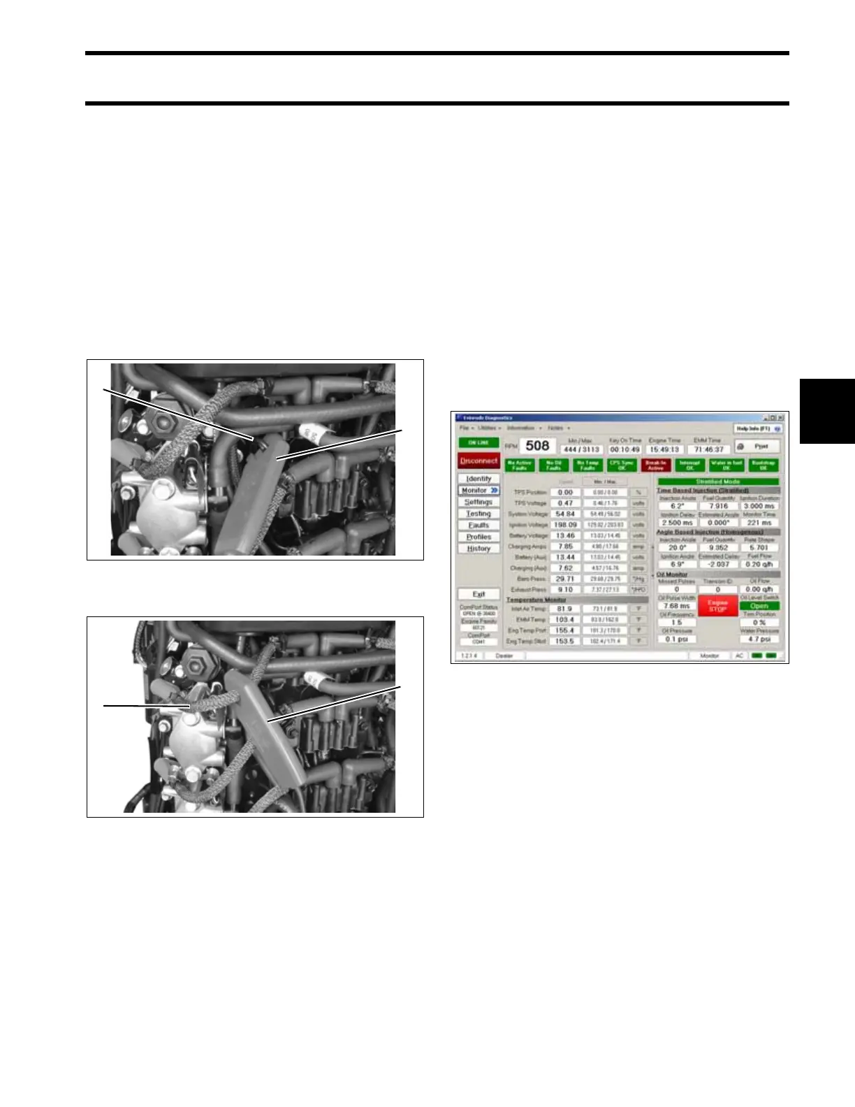
Engine Monitoring Information
Use the Evinrude Diagnostics Software program
to access the engine Monitor screen. This screen
display provides engine information as it is occur-
ring. Circuits are monitored for actual voltages or
the condition of the circuit. Switch and sensor cir-
cuits, battery voltage (12 V), system voltage
(55 V), and ignition voltage (200 V) are continu-
ously monitored.
IMPORTANT: The engine Monitor screen of the
diagnostics program does not offer voltage infor-
mation for all circuits.
1. Timing light pick-up
2. Ignition coil primary wire
005318
1. Timing light pick-up
2. Secondary, high tension wire
005319
1
2
1
2
Engine Monitor Screen 005141