241
POWERHEAD
DISASSEMBLY
10
Allen 1/4 in. hexagonal wrench. Attach suitable
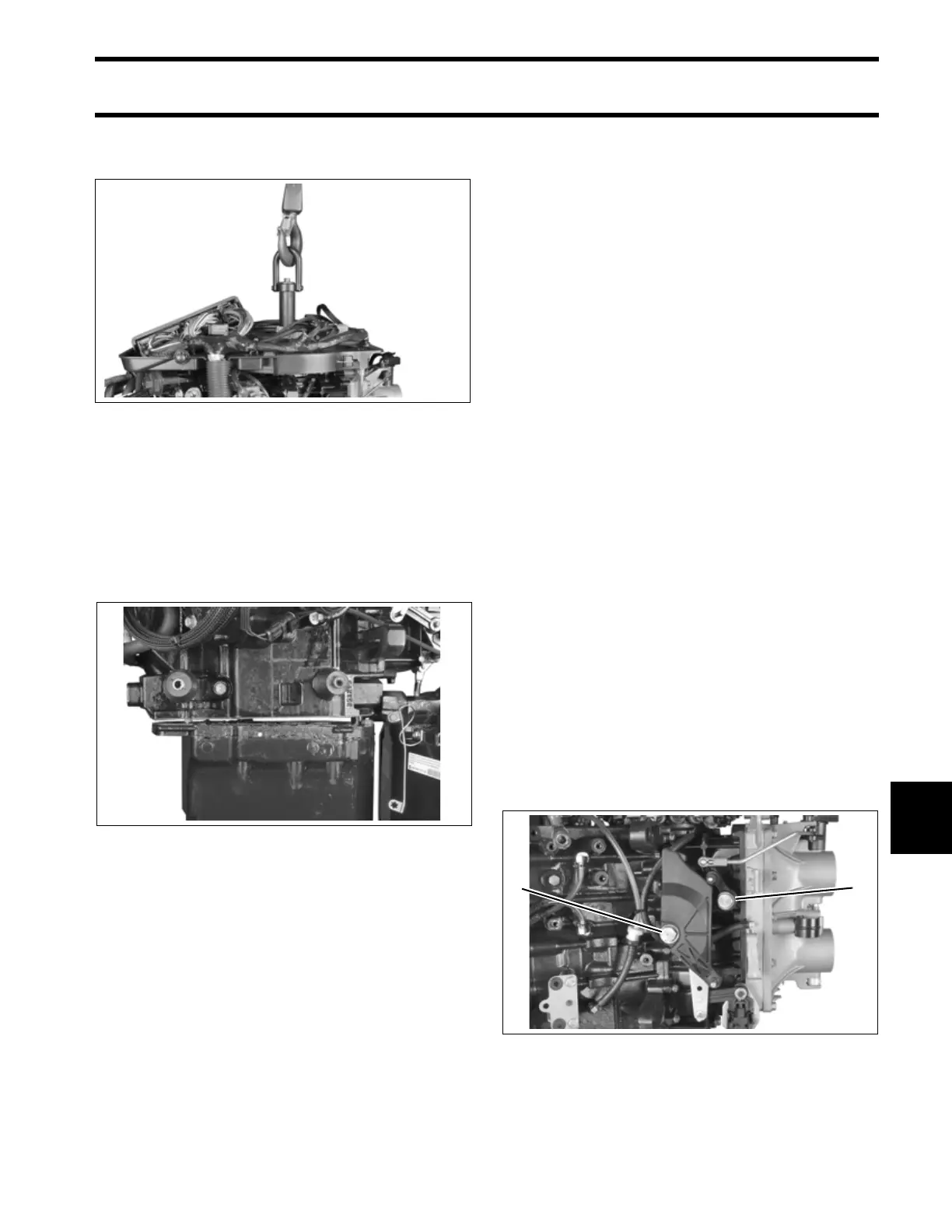
chain hoist to lifting tool.
With weight of powerhead supported by hoist, use
a suitable tool to carefully separate the power-
head from exhaust housing.
IMPORTANT: Do not damage the powerhead
adapter mating surfaces when separating.
Remove the powerhead.
DISASSEMBLY
General
To simplify reassembly and wiring installation, lay
out the various screws and clamps in the order of
their proper location.
Remove the electric starter. Refer to Starter
Removal on p. 161.
Remove fuel pump assemblies, fuel manifolds,
and filter. Refer to FUEL COMPONENT SERVIC-
ING on p. 189.
Remove EMM, then remove electrical harness
with flywheel cover base, starter solenoid, and
trim relay module.
Remove flywheel and stator. Refer to FLYWHEEL
AND STATOR SERVICING on p. 154.
Remove oil pump, rear oil manifold, and oil circu-
lation hoses. Refer to OIL COMPONENT SER-
VICING on p. 222.
Remove ignition coils and fuel injectors. Refer to
Fuel Injectors on p. 193.
IMPORTANT: Mark injectors for proper cylinder
location before removal. All injectors must be rein-
stalled in their original location. Improper injector
installation can result in powerhead failure.
Remove throttle cam screw and throttle lever
screw.
005260
005259
1. Throttle cam screw
2. Throttle lever screw
005293
21