348
GEARCASE
COUNTER ROTATION
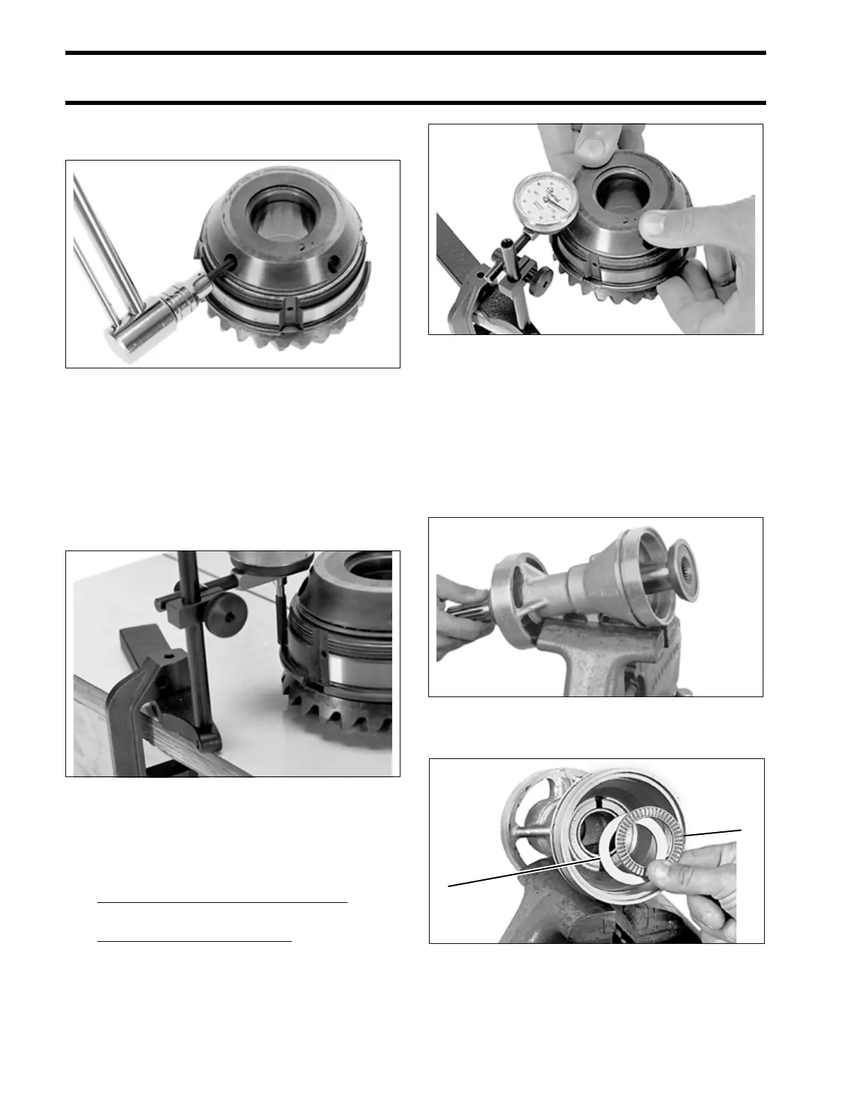
Install set screws and torque to 144 to 168 in. lbs.
(16.3 to 19 N·m). Use no thread sealant.
Anchor a dial indicator gauge to a flat, level sur-
face.
Position the gear assembly so the indicator nee-
dle makes contact with the flange on the housing.
The indicator needle must be parallel with the side
of the gear housing and perpendicular to the table
surface. Zero the dial indicator.
Grip the bearing housing 180° apart and pull up to
get a reading on the indicator. To determine thick-
ness of shims; use the following example:
0.030 in. of shims in the assembly
– 0.020 in. reading on the dial indicator
= 010 in. difference
+ 0.001 in. necessary end play
= 0.011 in. required shims
Remove the 0.030 in. (0.7 mm) of shims from the
assembly. Reassemble the gear assembly using a
combination of shims to achieve the required
thickness. Apply Nut Lock to the threads of the set
screws and torque to 144 to 168 in. lbs. (16.3 to
19 N·m).
Push propeller shaft out of the bearing housing.
Remove the thrust washer and thrust bearing.
31967
31953
31968
13479
1. Thrust washer
2. Thrust bearing
13593
2
1