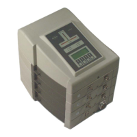
HPPR/2
24 / 92 H172204_1_001
The status LEDs ERROR and READY indicate the current state of the Cover2‘s host. In
AVANCE NEO systems the host firmware is located in the EPU.
The LCD‘s wobble tab shows the reflection coefficient of the probe during wobbling.
The individual modules, the power transmitter and the probe are connected with N-plugs and
shielded cables. The BNC cable for the receiver signal leads from the rear HPPR/2
BASEPLATE AV4 unit to the FT and lock receivers in the console. The connected multi-core
cable supplies all DC voltages for the preamplifier modules. The cable also contains the
required real time pulses (LOCK_PP, RCP_HPPR_Mode) and a BFB-Bus for command and
data transfer between the console and the HPPR/2. Tune and RGPs are transferred via a
special cable from the console to the HPPR/2.
5.2 Features
• Same RF technology as the classic HPPR.
• Ease of operation.
• Self configuration.
• Modular arrangement, up to 8 preamplifier modules per HPPR/2, even identical ones.
• Enhanced noise immunity (also Cover Module).
• Enhanced display information.
• Integration of external functional modules as ATMA and Cryoprobe.
5.3 HPPR/2 RF Power Supervision
Introduction
Some of the HPPR/2 modules (AQS 1H2H modules and HPLNA 1H) have a built in,
calibrated RF power limit detection capability. This power limit detection capability is used to
supervise the power applied to the probe (calibrated and referenced at the probe connector
of the HPPR/2 module), but also to protect the appropriate HPPR/2 module from too much
power applied.
The transmission of RF power through the HPPR/2 module is being monitored autonomously
(supervision is enabled after power up) and in case of exceeding power, the emergency stop
signal will be activated. After a latency of about 2-3us all RF pulses and RF sources will be
stopped.
RF Power
In order to avoid too much power to be applied to the probe, the power limit detection
thresholds of the HPPR/2 modules for continuous (CW) and peak (PK) power are set
according to the probe connected to the HPPR/2.
For each probe connected to the HPPR/2 COVER2 MODULE the PICS entries of that probe
are read out by the firmware of the HPPR/2. The values for continuous but also peak power
are extracted from the $PChan group for each nucleus. Afterwards, the threshold values for
the power limit detection are set for each nucleus (if power limit detection is available)
according to the probe power values.
To avoid an emergency stop too close at the probe power limits, a 2 dB for peak power
respectively a 3 dB for continuous power margin is added for the power limit detection
thresholds.

 Loading...