Home
Bruker
Laboratory Equipment
HPPR/2
Page 43 (HPPR;2 Operating Modes)
Bruker HPPR/2 - HPPR;2 Operating Modes
92 pages
Manual
To Next Page
To Next Page
To Previous Page
To Previous Page
Loading...
HPPR/2 Preamplifier Modules for AVANCE NEO
H172204_1_001
43 / 92
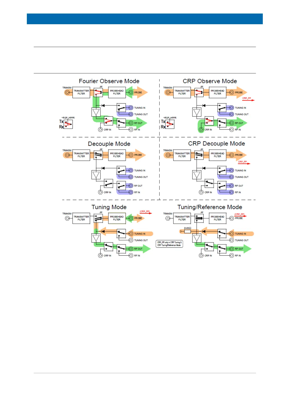
7.4
HPPR/2 Operating Modes
7.4.1
Operating Modes of HPPR/2 XBB, 31P, 13C, 15N Modules
Figure7.2: Operating Modes of HPPR/2 XBB19F, 31P, 13C, 15N Modules
42
44
Table of Contents
Main Page
Table of Contents
3
1 About this Manual
7
Symbols and Conventions
7
2 Introduction
9
Intended Use
9
Installation and Initial Commissioning
9
Limitation of Liability
9
Warranty Terms
10
Customer Service
10
Product Safety and Electromagnetic Compatibility
10
3 Safety
11
General
11
System Owner's Responsibility
11
Personnel Requirements
12
Qualifications
13
Unauthorized Persons
13
Instruction
13
Personal Protective Equipment
14
Location of the Safety Label
14
Basic Dangers
14
General Workplace Dangers
14
Dangers from Electric Power
15
Danger from Magnetic Fields
16
Environmental Protection
16
Signs and Labels
17
4 Transport, Packaging and Storage
19
Symbols on the Packaging
19
Inspection at Delivery
20
Table 4.1: Symbols on the Packaging
20
Packaging
21
Storage
21
5 Hppr/2
23
Overview
23
Figure 5.1: HPPR/2 Standard Configuration
23
Features
24
HPPR/2 RF Power Supervision
24
Figure 5.2: Threshold for RF Power Versus Pulse Length
25
Figure 5.3: Cover2: Threshold Power Display
25
Faqs
26
HPPR/2 Wiring
27
Figure 5.4: Module Connection
27
Supply and Pulse Wiring (up to 4 RF Channels)
28
Figure 5.5: Standard Wiring HPPR/2
28
Table 5.1: Part List HPPR/2 Wiring
28
Supply and Pulse Wiring (5 to 8 RF Channels)
29
Figure 5.6: Standard Wiring: HPPR/2
29
Table 5.2: Part List HPPR/2 Wiring
29
Wobble
30
Abbreviations
30
Table 5.3: Abbreviations
31
6 Cover2 Module
33
Front View
33
Figure 6.1: Cover Module Front View
33
Cover2 and Display Versions
34
LED Description
34
Table 6.1: Part Numbers: HPPR/2 Cover2
34
Table 6.2: LED States
34
LCD and Touch Screen Description
35
Service Tab
35
Figure 6.2: Service Tab
35
Table 6.3: LCD and Touch Screen Description
35
Modules Tab
36
Figure 6.3: Modules Tab
36
Table 6.4: Modules Modes
36
Devices Tab
37
Wobble Tab
37
Figure 6.4: Devices Tab
37
Figure 6.5: Wobble Tab
37
Rear View
38
Figure 6.6: Cover2 Module Rear View
38
Rear Side Connectors
39
Table 6.5: Connectors on the Rear Side
39
Table 6.6: Appropriate Cable for Connected Devices
39
Left Side Connectors
40
Functionality
40
Power Supply and Monitoring
40
Real Time Pulse
40
Bis
40
Table 6.7: Connectors on the Left Side
40
Table 6.8: Power Supply Error Cause
40
7 HPPR/2 Preamplifier Modules for AVANCE NEO
41
HPPR/2 Preamplifier Variants
41
HPPR/2 Preamplifier Part Numbers
41
Table 7.1: HPPR/2 Modules for HR NMR, Solids and Imaging
41
HPPR/2 Preamplifier Overview
42
Figure 7.1: Preamp Module (Open Example)
42
Table 7.2: AQS Preamplifier for HR NMR (Nanobay)
42
Table 7.3: HPPR/2 Modules for MRI
42
HPPR/2 Operating Modes
43
Operating Modes of HPPR/2 XBB, 31P, 13C, 15N Modules
43
Figure 7.2: Operating Modes of HPPR/2 XBB19F, 31P, 13C, 15N Modules
43
Operating Modes of HPPR/2 2H Module
44
Figure 7.3: Operating Modes of HPPR/2 2H Modules
44
Operating Modes of AQS 1H2H Preamp
45
Figure 7.4: Operating Modes of AQS 1H2H Preamp
45
Figure 7.5: Operating Modes of AQS 1H2H Preamp
46
Operating Modes of HPLNA 1H Module (ECL >=06, with Lock Capability)
47
Figure 7.6: Operating Modes 1H HPLNA Module
47
Technical Specifications
48
Technical Data AQS 1H2H Preamp (ECL>=03)
48
Figure 7.7: Operating Modes 1H HPLNA Module
48
Table 7.4: Technical Data AQS 1H2H Preamp
48
Technical Data AQS XBB19F 2HS MODULE (ECL>=07)
49
Technical Data HPPR/2 1H HPLNA MODULE (19F-1H)
49
Table 7.5: Technical Data AQS XBB19F 2HS Preamp
49
Table 7.6: Technical Data HPPR/2 1H HPLNA Module
49
Technical Data HPPR/2 3H HPLNA MODULE
50
Technical Data HPPR/2 31P MODULE (ECL>=07)
50
Technical Data HPPR/2 13C MODULE (ECL>=08, 79Br-13C)
50
Table 7.7: Technical Data HPPR/2 3H HPLNA Module
50
Table 7.8: Technical Data HPPR/2 31P Module
50
Table 7.9: Technical Data HPPR/2 13C Module
50
Technical Data HPPR/2 2H MODULE (ECL>=07)
51
Technical Data HPPR/2 15N MODULE (ECL>=07)
51
Table 7.10: Technical Data HPPR/2 2H Module
51
Table 7.11: Technical Data HPPR/2 15N Module
51
Technical Data HPPR/2 XBB19F 2HP MODULE (ECL>=07)
52
Technical Data HPPR/2 XBB31P 2HP HPLNA MODULE
52
Table 7.12: Technical Data HPPR/2 XBB19F 2HP Module
52
Table 7.13: Technical Data HPPR/2 XBB31P 2HP HPLNA Module
52
RF Pulse Power Capability Overview
53
8 HPPR/2 Baseplate AV4
55
Overview
55
Figure 8.1: View BASEPLATE AV4 4CH
55
Figure 8.2: View BASEPLATE AV4 8CH
55
Description
56
Part Numbers
56
Technical Data
56
Troubleshooting
56
Table 8.1: Part Numbers: BASEPLATE AV4
56
9 CRP RF-Electronics
57
General
57
Power Consumption
57
Table 9.1: CRP RF-Electronics Power Consumption
57
Transmit-/Receive Bias Currents
58
Table 9.2: Cryoprobe T/R-Switch Bias Currents for the HPPR/2 Family
58
10 MRI Active Detuning Module
59
Overview
59
Figure 10.1: View HPPR/2 MRI ACTIVE DETUNING Module
59
Description
60
Input Pulses
60
Figure 10.2: Block Diagram: MRI ADM-CRP Module (ECL > 03)
60
PIN Driver Function
61
Tune/Match Driver Function
61
RGP Output Pulse
61
Figure 10.3: PIN-Driver Overcurrent Error Handling
61
Connectors
62
Part Numbers
62
Technical Data
62
Table 10.1: Connector Description
62
Table 10.2: Part Number: ADM
62
Coil Control Section
63
RF-Section
64
Troubleshooting
64
Diagnostics
64
Figure 10.4: RF Measurement Paths
64
11 HPPR/2 MRI ADM-CRP Module
65
Overview
65
Description
65
Figure 11.1: View HPPR/2 MRI ADM-CRP Module
65
Figure 11.2: Block Diagram: MRI ADM-CRP Module
65
Tuning/Matching Driver
66
Operating Modes
66
Table 11.1: Module Operating Modes
66
Connectors
67
Part Numbers
67
Table 11.2: Connector Description
67
Table 11.3: Part Numbers: ADM-CRP
67
Technical Data
68
Troubleshooting
68
Diagnostics
68
12 HPPR/2 MRI Baseplate AV4
69
Overview
69
Figure 12.1: View MRI BASEPLATE AV4 4CH
69
Figure 12.2: View MRI BASEPLATE AV4 8CH
69
Description
70
Figure 12.3: Internal Wiring: MRI BASEPLATE AV4 4CH & 8CH
70
Connectors
71
Part Numbers
71
Technical Data
71
Figure 12.4: Rear View MRI BASEPLATE AV4 4CH and 8CH
71
Table 12.1: Pinout RGP HPPR in Connector
71
Table 12.2: Part Numbers: MRI BASEPLATE AV4
71
Troubleshooting
72
13 Maintenance
73
Cleaning
73
Before Cleaning
73
Cleaning the Outer Shell of the Device
73
Other Cleaning Operations
73
Table 13.1: Maintenance Schedule for Laboratory Personnel
73
Preventative Maintenance
74
Bruker Service Maintenance
74
Device Report File
74
Firmware Update
74
14 Troubleshooting
75
Operation Failure
75
Hardware Warnings or Errors
75
Figure 14.1: Troubleshooting: Topspin Event Messages
75
Figure 14.2: Troubleshooting: Service Web Event Messages
75
Troubleshooting Hardware Problems
76
Service Web
76
Savelogs
76
Aqrackserver Log
76
How to Report a System Error
77
15 Dismantling and Disposal
79
Dismantling
79
Disposal Europe
79
Disposal USA and Other Countries
80
16 Technical Data
81
General Information
81
Connection Values
81
Table 16.1: Technical Data: General Information
81
Table 16.2: Electrical Connection Values
81
Operating Conditions
82
Rating Plate
82
Figure 16.1: Rating Plate HPLNA 1H Module
82
Table 16.3: Operating Environment
82
17 Contact
83
List of Figures
85
List of Tables
87
Index
89
Related product manuals
Bruker BSMS/2
61 pages
Bruker BPHG 90
78 pages
Bruker NMR CASE
15 pages
Bruker DektakXT
83 pages
Bruker IFS 125M
228 pages
Bruker D2 PHASER
120 pages
Bruker D8 Series
96 pages
Bruker CryoProbe
107 pages
Bruker AVANCE NEO
120 pages
Bruker Anton Paar
136 pages
Bruker QUANTAX EDS
119 pages
Bruker Ascend 400'54
102 pages