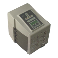
MRI Active Detuning Module
H172204_1_001 63 / 92
10.3.1 Coil Control Section
Input Signals:
RGP_HPPR: RS-422 differential --
EXT_RGP(1:2)~: +5V TTL --
AD-CTRL(1:4)~: +5V TTL --
LOGIC_SEL: (from coil connector) open/1kΩ pull-down or +5V
TTL
--
PIN Driver:
Positive (forward) output voltage: (voltage
mode)
+4 .. 5.5 Vdc
Positive (forward) output current: (voltage
mode)
max. 500 mA
Positive (forward) output current: (current
mode)
limited to 100
3
mA
Negative (reverse) output voltage: (-36 V
mode)
-36 +3/-10% Vdc
Negative (reverse) output voltage: (-60 V
mode)
-60 +3/-10% Vdc
Negative (reverse) output current: (-60 V
mode)
max. -50 mA
Transition time: (50% input pulse -> 90%
output voltage)
max. 3 µs
Tuning/Matching Driver:
Output voltage: (DAC 0..4095, register A or B) 0..-30
4
Vdc
Trans. time reg. A to B: (50% input pulse ->
90% output voltage)
max. 30 µs
Tune control output signals: +5V TTL --
Coil Control Signals:
RGP output voltage: +5V TTL --
+9V output voltage: (I
Lmax
= 200 mA) +9.0 ±0.5 Vdc
-30V output voltage: (I
Lmax
= 20 mA) -30.0 ±0.5 Vdc
+5V output voltage: (I
Lmax
= 50 mA) +5.0 ±0.5 Vdc
3
ECL02: max. current = 108 .. 124 mA; ECL03: max. current = 104 .. 110 mA
4
Transition time corrected (old value = max. 6 µs)

 Loading...