MRI Active Detuning Module
H172204_1_001 61 / 92
10.2.2 PIN Driver Function
Each driver can be controlled independently either in static mode or by the input pulses,
which can be OR combined via software setting. The pulse polarity is either set via the
LOGIC_SEL input from the coil connector or via software.
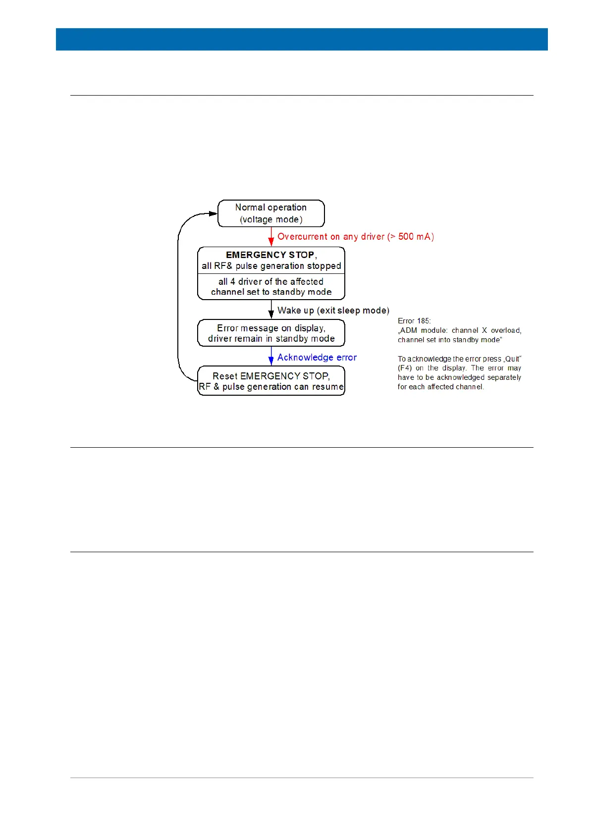
The positive (forward) output voltage level is about +5 V, depending on the load current. In
voltage mode the maximum load current is 0.5 A per driver. In current mode the load current
is limited to 100 mA per driver. The negative (reverse) output voltage level can be set either
to -36 V or -60 V.
Figure10.3: PIN-Driver Overcurrent Error Handling
10.2.3 Tune/Match Driver Function
Each coil channel has four DAC controlled tuning drivers for varicap diodes: Tune 0°, Match
0°, Tune 90°and Match 90°. The output voltage level is between 0 and -30 V.
Each DAC has two data registers A and B. This allows fast switching between two preset
output voltages. To toggle between these, any OR-combination of the input pulses can be
used.
10.2.4 RGP Output Pulse
Each coil channel has one RGP output pulse. The pulse can be selected from the three input
pulses RGP_HPPR, EXT_RGP(1)~ or EXT_RGP(2)~ individually for each channel.

 Loading...


