Sensor Configuration and Numbering
SMART MATRIX - 2-15 -
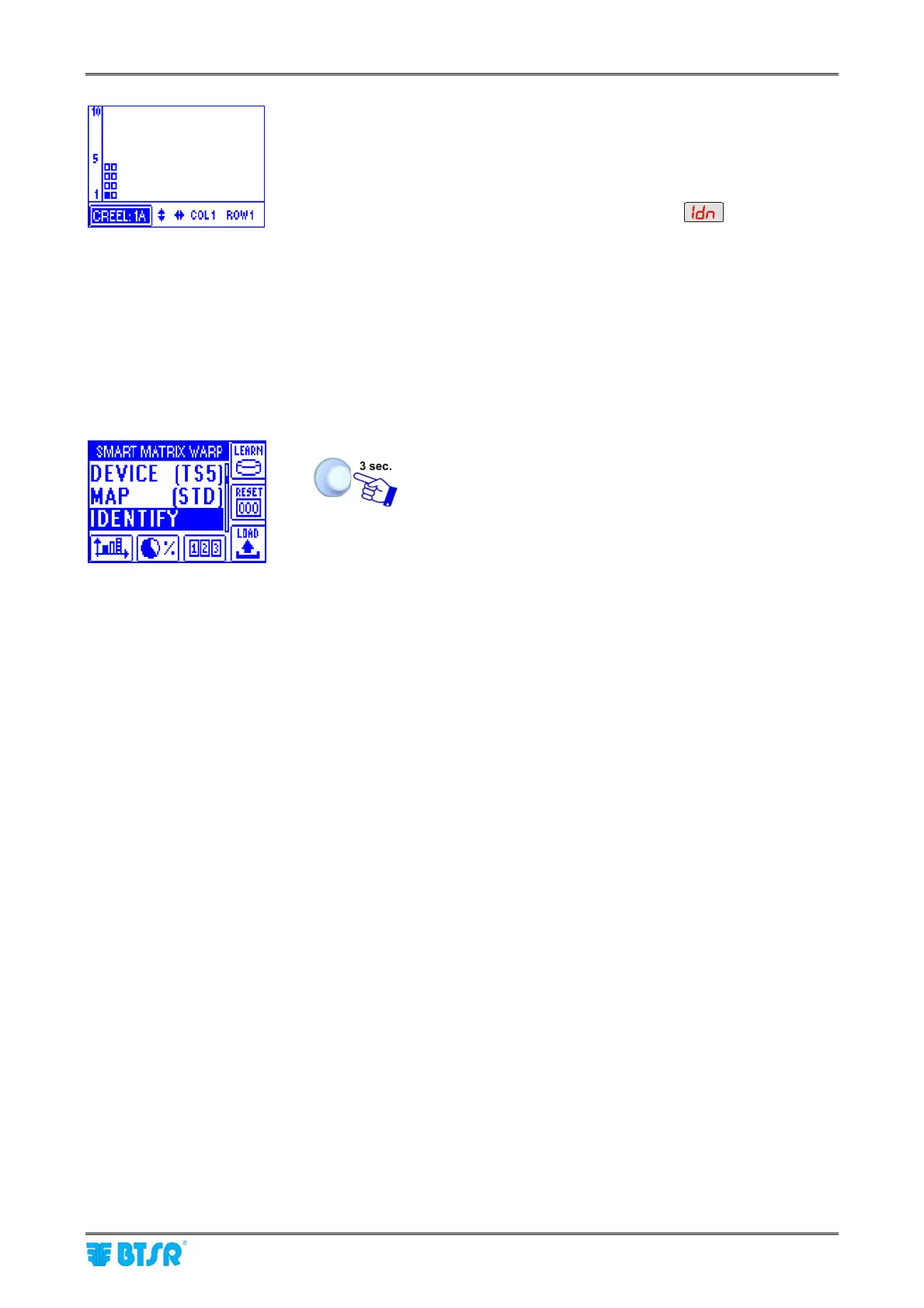
• The example shown indicates that the numbering
(identification) procedure of the 8 sensors belonging to
creel 1A is going to start. The flashing small square
indicates the sensor located on “Column 1 - Row 1 -
Creel 1A”.
• The display of all Boards will show
• The green led will flash on all sensors.
• Shim the touch light of the sensor corresponding to
“Column 1 - Row 1 - Creel 1A” position; The sensor’s
led changes from flashing green to red.
• On SMART MATRIX display the small square of sensor
located on “Column 1 - Row 2 - Creel 1A” starts flashing.
• Shim the touch light of the relevant sensor and continue
with the numbering of all sensors.
At the end of the numbering operation, the configuration
menu will re-appear.
To return to CONTROL status.