Section 13. Implementing Advanced Communications Links
13.1.3.1 Hardware Setup
The RF modem in the RF Base has to be configured to work in Synchronous
Device Communication (SDC) mode. This is done by changing the 9
th
DIP
switch inside the RF Base modem to a 0 or closed. This will allow the
datalogger to pass communication to the RF Base.
SDC mode cannot be used with 21X or CR7 dataloggers or any
of the table based dataloggers.
NOTE
The datalogger and the RF base must both be connected to the remote phone
modem on the same 9 pin ribbon cable.
13.1.3.2 Network Setup in LoggerNet
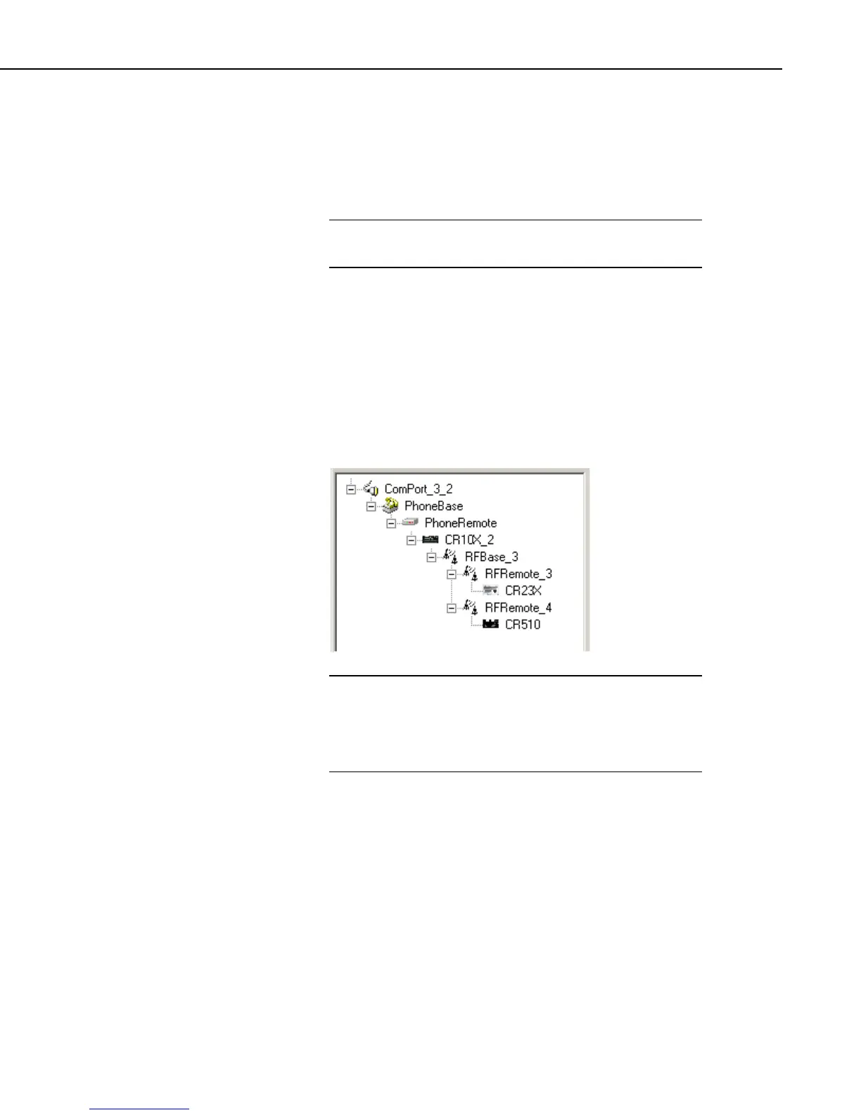
Setting up a datalogger at the RF base in a Phone to RF system requires that the
datalogger be connected as a child of the remote phone modem, and the RF
Base be connected as a child of the datalogger. Then the RF network is
connected to the RF Base. An example of this type of configuration is shown
below.
In Phone to RF systems with a datalogger at the RF base, you
should set all three levels of datalogger security so the computer
has to unlock the datalogger before getting data. This will
prevent a situation where the computer can be getting data from
the wrong datalogger when a connection to a remote station fails.
NOTE
13.2 Phone to MD9
13.2.1 Setup
The device map for a phone to MD9 link would look similar to the
communications network below.
13-3
 Loading...