Section 13. Implementing Advanced Communications Links
collection for the anticipated amount of data. If the Max Time Online is
reached, LoggerNet will force the connection to close, even if it is in the
middle of collecting data.
13.2.2.5 1Grounding
Depending on the configuration and distance of the MD9 network, be sure to
follow the grounding guidelines provided in the MD9 hardware manual.
Grounding issues have been known to prevent reliable communications and
data collection.
13.3 TCP/IP to RF
The development of Serial Server devices that allow serial communications
devices to be connected to TCP/IP networks now allows an RF network to be
connected to the LoggerNet server over the Internet or across a Local Area
Network. A Serial Server has a standard TCP/IP connection on one side and
one or more serial ports, typically RS232, on the other. This type of network
setup is typically used for organizations that have field offices or stations that
are connected together by a TCP/IP network. This allows the LoggerNet
server computer to be located in a central area for administration while
providing communications to remote RF networks.
13.3.1 Setup
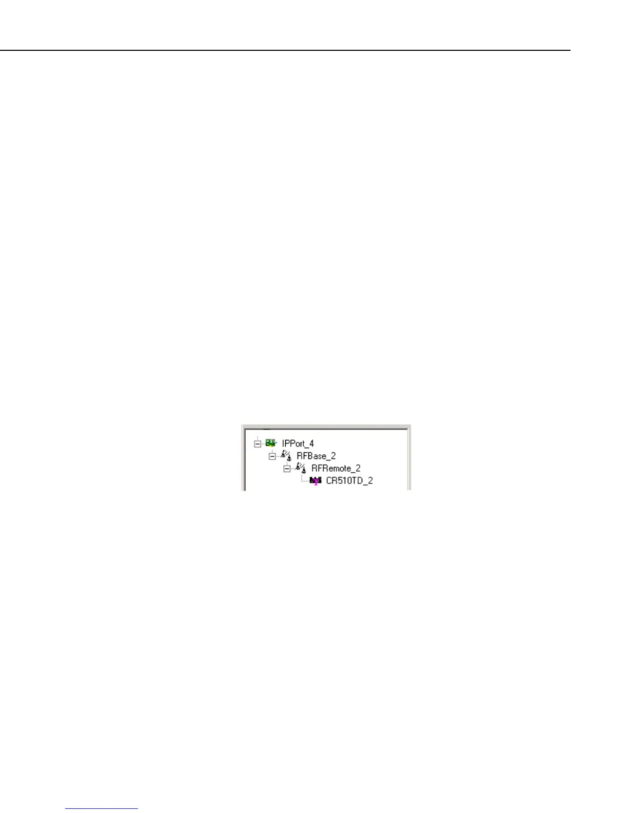
The device map set up in the Setup Screen for a TCP/IP to RF link would look
similar to the communications network below.
To begin, add an IPPort to the device map if one does not exist. Add an RF
base modem to the IPPort, and to this, add the remote RF modem. To
complete the network, add your datalogger to the remote RF modem. Review
all of the settings for each device, and make any changes to customize the
settings for your network configuration.
13.3.2 Operational Considerations
There are several settings that should be configured to optimize the TCP/IP to
RF network.
The BMP1 Low Level Packet Delay is configured on the datalogger’s
hardware tab. This governs how rapidly handshaking packets are exchanged
by the server and the RF base while a datalogger transaction is pending. By
default there is no delay so these packets pass back and forth about 5 or 6 times
a second. For TCP/IP communications this should be slowed down by setting
the number of milliseconds to wait to at least 1000 (1 second delay).
13-5