COPYRIGHT
©
1999 CANON INC. CANON GP160 REV.0 FEB. 1999 PRINTED IN JAPAN (IMPRIME AU JAPON)
CHAPTER 2 BASIC OPERATION
2-8
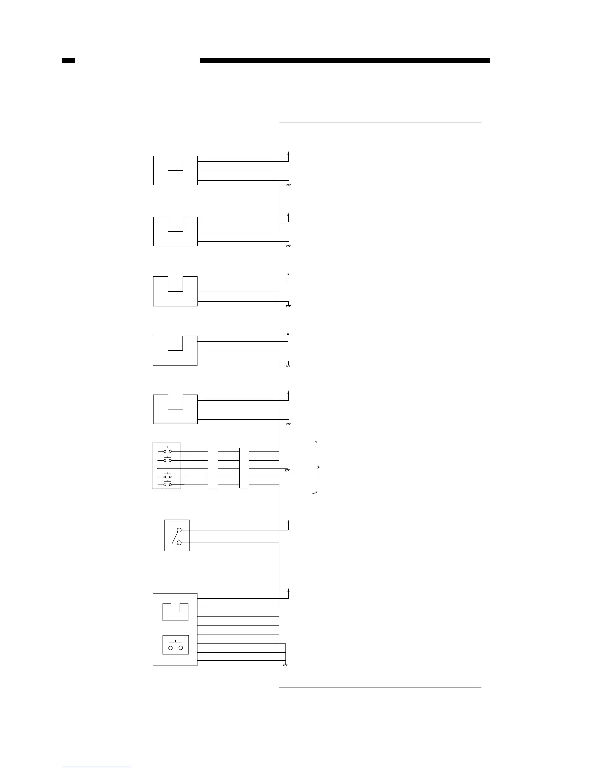
DC controller PCB input / output (1/3)
Figure 2-503
DC controller PCB
J306-1
-2
-3
+5V
PS301S*
Paper leading
edge sensor
PS301
Registration sensor
PS302
Paper sensor
PS303
Paper width sensor
PS304
Cassette
paper sensor
PS305
SW301
J303-1
-2
-3
J303-4
-6
-5
When the unit is on standby,
this sensor detects right lower cover
open / close
J306-4
+5V
PS302S*
PS303S*
+5V
+5V
PS304S*
PS305S
-5
-6
J306-7
-8
-9
+5V
Cassette paper size
detection switch
J302-1
-2
-4
-5
-3
PSIZ3
PSIZ2
PSIZ1
PSIZ0
J312-4
-1
+24V
CVROPN
Sensor printed circuit board
PS501
SW501
Multi-feeder
paper sensor
Test print
output switch
J309-8
+5V
-7
PS501S*
-2
TSTON*
-6
-3
-1
-4
-5
When the PS301 detects paper: “0”
(When the light-blocking plate
is not in PS301)
When the PS302 detects paper: “0”
(When the light-blocking plate
is not in PS302)
When the PS303 detects paper: “0”
(When the light-blocking plate
is not in PS303)
When the PS304 detects paper: “0”
(When the light-blocking plate
is not in PS304)
When paper is in the cassette: “1”
(When the light-blocking plate
is in PS305)
Refer to P.7-6
When the front cover is open: “1”
When paper is in the cassette: “0”
(When the light-blocking plate
is not in PS501)
When the switch is pushed: “0”
Front cover open /
shut sensor
 Loading...