COPYRIGHT
©
1999 CANON INC. CANON 405/335 REV.0 JAN. 1999 PRINTED IN JAPAN (IMPRIME AU JAPON)
11-9
CHAPTER 11 SYSTEM INTEGRATION
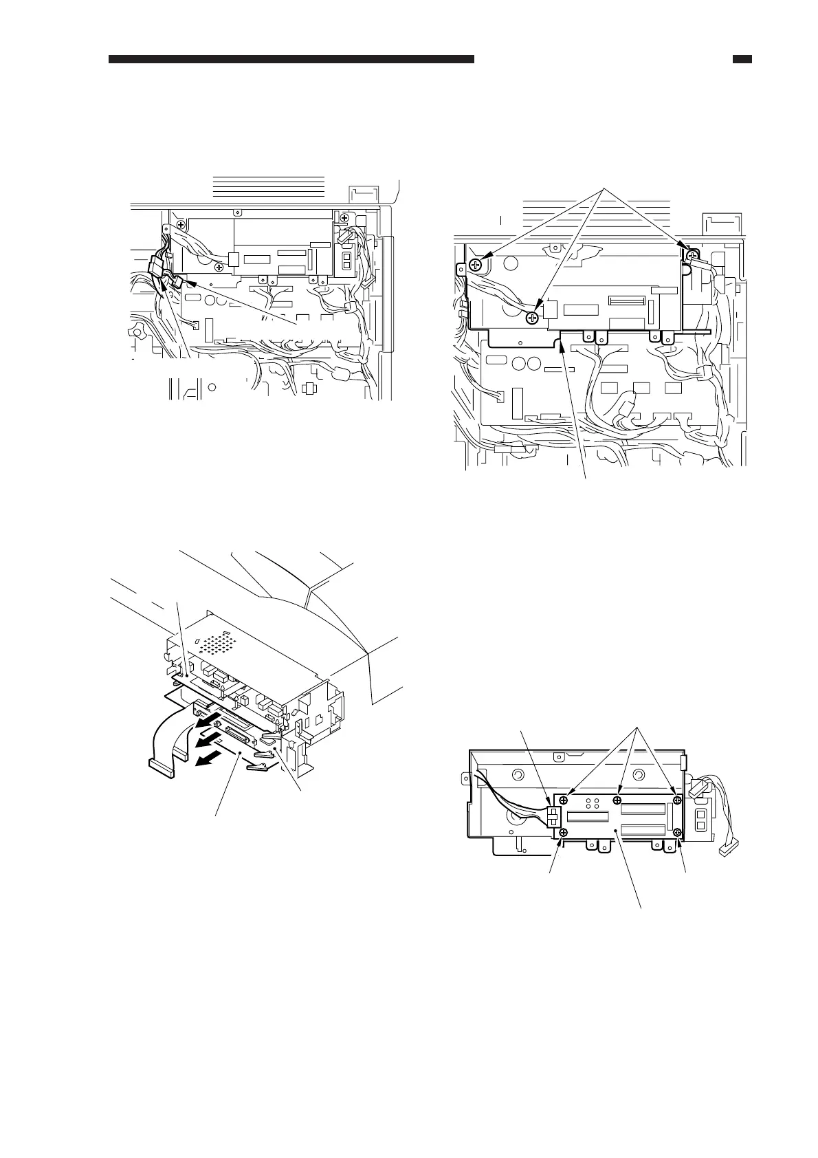
5) Disconnect the two connectors shown in
the figure.
Figure 11-305
6) If any boards exist in the extension case,
remove them.
7-pin connector
2-pin connector
Figure 11-306
Fax board
SCSI board
Interface board
7) Remove the three screws, and detach the
extension unit from the copier.
Figure 11-307
2. Removing the System Motherboard
1) Remove the extension unit.
2) Remove the accessory boards from inside
the extension unit.
3) Remove the five screws, and disconnect
the connector; then, detach the system
mother board from the extension unit.
Screws (w/ washer)
Extension unit
Figure 11-308
Screws
Screw
Screw
System motherboard
Connector
 Loading...