122 Functionality CG Drives & Automation, 01-5980-01r2
(CA1&F1)+(T1Q&!A2)
With the above values inserted the resulting logic expression
now becomes:
which is equal to 1.
Logic 1 Input 1 [6212]
In this menu the first input for the Logic 1 function is
selected. The same selections are valid for [6214] L1 Input 2,
[6216] L1 Input 3, and [6218] L1 Input 4.
This table is also valid for the input signals in logic functions
2 [622], 3 [623], and 4 [624], however default values vary.
See Menu List in Appendix 1.
Note that a logic function can not directly use itself as an
input signal, e.g. for the L1 Input, it will not be possible to
choose L1 or !L1.
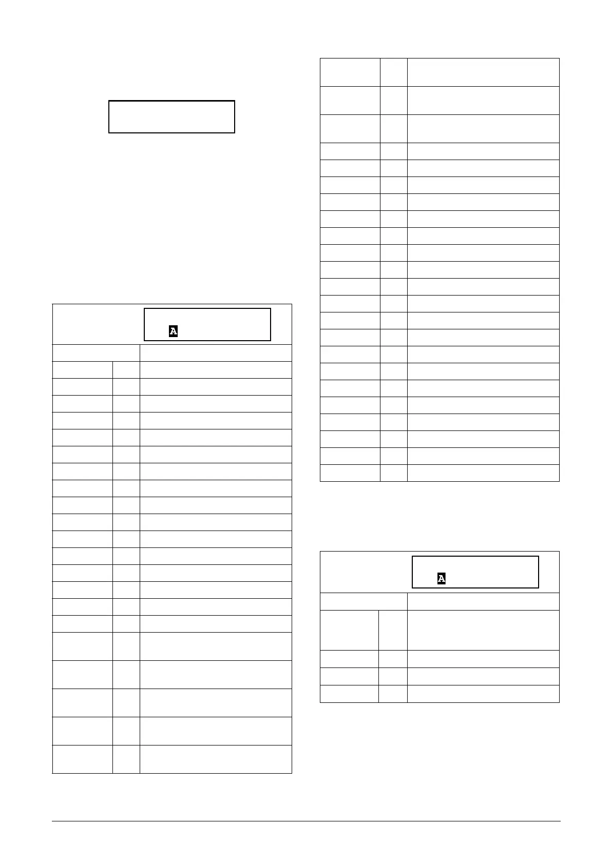
Logic 1 Operator 1 [6213]
In this menu the first operator for the Logic 1 function is
selected.
Default: CA1
CA1 0 Analogue comparator 1 output.
!A1 1 Analogue comp 1 inverted output.
CA2 2 Analogue comparator 2 output.
!A2 3 Analogue comp 2 inverted output.
CA3 4 Analogue comparator 3 output.
!A3 5 Analogue comp 3 inverted output.
CA4 6 Analogue comparator 4 output.
!A4 7 Analogue comp 4 inverted output.
CD1 8 Digital comparator 1 output.
!D1 9 Digital comp 1 inverted output.
CD2 10 Digital comparator 2 output.
!D2 11 Digital comp 2 inverted output.
CD3 12 Digital comparator 3 output.
!D3 13 Digital comp 3 inverted output.
CD4 14 Digital comparator 4 output.
!D4 15 Digital comp 4 inverted output.
L1 16
Logic output 1.
Not used for Logic 1.
!L1 17
Logic output 1 inverted.
Not used for Logic 1.
L2 18
Logic output 2.
Not used for Logic 2.
!L2 19
Logic output 2 inverted.
Not used for Logic 2.
L3 20
Logic output 3.
Not used for Logic 3.
621 Logic 1
Stp (1&1)+(1&0)
!L3 21
Logic output 3 inverted.
Not used for Logic 3.
L4 22
Logic output 4.
Not used for Logic 4.
!L4 23
Logic output 4 inverted.
Not used for Logic 4.
T1Q 24 Logic timer 1 output
!T1Q 25 Inverted logic timer 1 output
T2Q 26 Logic timer 2 output
!T2Q 27 Inverted logic timer 2 output
T3Q 28 Logic timer 3 output
!T3Q 29 Inverted logic timer 3 output
T4Q 30 Logic timer 4 output
!T4Q 31 Inverted logic timer 4 output
F1 32 Flip-flop output 1.
!F1 33 Flip-flop output 1 inverted.
F2 34 Flip-flop output 2.
!F2 35 Flip-flop output 2 inverted.
F3 36 Flip-flop output 3.
!F3 37 Flip-flop output 3 inverted.
F4 38 Flip-flop output 4.
!F4 39 Flip-flop output 4 inverted.
CTR1 40 Counter output 1.
!CTR1 41 Counter output 1 inverted.
CTR2 42 Counter 2 output.
!CTR2 43 Counter output 2 inverted.
Default: &
·
0
When · (dot) is selected, the Logic 1
expression is finished (when two or
three expressions are tied together).
& 1 &=AND
+ 2 +=OR
^3^=EXOR

 Loading...