10 Mounting CG Drives & Automation 01-5980-01r2
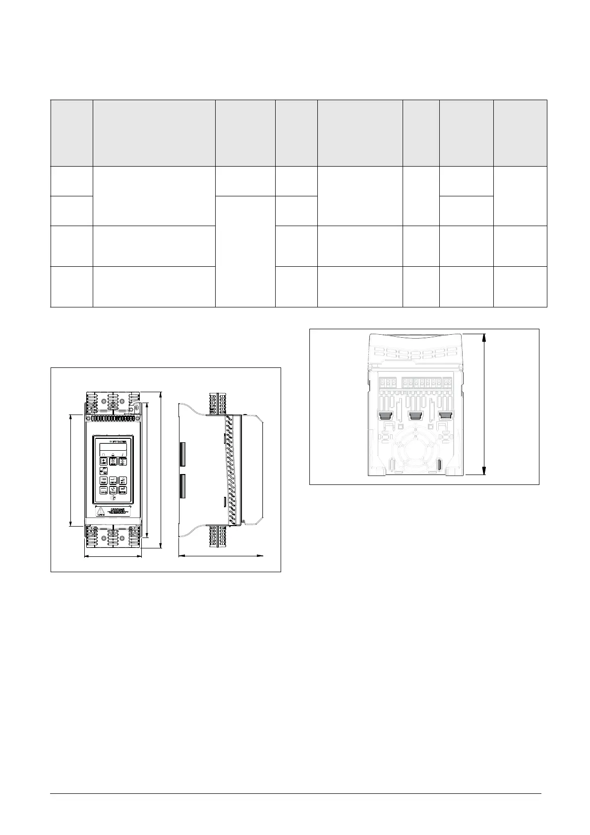
2.2 Mechanical specifications and drawings
*) H1 = Height of enclosure.
H2 = Total mounting height of unit.
H3 = Total height including Cable covers.
Emotron TSA frame size 1 - 2
Fig. 2 Dimensions for Emotron TSA frame size 1 and 2.
Fig. 3 Dimensions for Emotron TSA frame size 1 and 2,
bottom view.
Ta b l e 6
TSA
Frame
size
Dimensions*
H1/H2/H3 x W x D
[mm (in)]
Mounting
position
[Vertical/
Horizontal]
Weight
[kg(lb)]
Connection
busbars and
pressnut
dimension
[mm (in)]
PE
screw
Cooling
system
Protection
class
1
246/296/340 x 126 x 188
(9.7/11.7/13.4 x 5 x 7.4)
Vertical
5.5
(12.1)
15 x 2
(0.59 x 0.08)
M6 connection
M5
Convection
IP20
2
Vertical/
Horizontal
5.7
(12.6)
Fan
3
285/323/380 x 196 x 235
(11.2/12.7/14.9 x 7.7 x 9.3)
13
(28.7)
20 x 5
(0.8 x 0.20)
M10 connection
M8 Fan IP20
4
378/411/514 x 254 x 260
(14.9/16.2/20.2 x 10 x 10.3)
23.5
(51.8)
40 x 10
(1.6 x 0.39)
Ø 13 connection
M8 Fan IP20
 Loading...
