CG Drives & Automation, 01-5980-01r2 Functionality 109
Digital Input 2 [522] to Digital Input 4
[524]
Same function as DigIn 1[521]. Default setting for DigIn 2
[522] is “Stop”. For DigIn 3 [523] the default is “Set Ctrl 1”
and for DigIn 4 [524] the default is “Reset”.
Additional digital inputs [529] to [52E]
Additional digital inputs with I/O option board installed,
“B1 DigIn 1” [529] - “B2 DigIn 3” [52E]. “B” stands for
“board”, 1 and 2 is the number of the board which is related
to the position of the I/O option board on the option
mounting plate. The functions and selections are the same as
for “DigIn 1” [521]. Default settings are “Off”.
8.5.3 Analogue Output [530]
Submenu with all settings for the analogue output.
Selections can be made from application and softstarter
values, in order to visualise actual status. Analogue output
can also be used as a mirror of the analogue input.
Analogue Output Function [531]
Sets the function for the analogue output. Scale and range are
defined by “AnOut Advanced” settings [533].
AnIn Select 11
Activates/deactivates analogue input
defined in [513A].
Autoset 12
Activates autoset of load monitor alarm
levels according to menu group [417].
NOTE: Always edge controlled even though
level control may be chosen in menu [21A].
Spinbrake 13
See description Spinbrake, page 49. Can
be activated from inactive state (softstarter
stopped but motor rotating).
Ext. Alarm 1 16
Be aware that if there is nothing connected
to the input, the softstarter will trip at
“External Alarm 1” immediately.
NOTE: The External Alarm 1 is active low.
NOTE: Activated according to “OR” logic.
See menu [2549].
Ext. Alarm 2 17
Be aware that if there is nothing connected
to the input, the softstarter will trip at
“External Alarm 2” immediately.
NOTE: The External Alarm 2 is active low.
See menu [254A].
Timer 1 18
Timer 1 [6311] will be activated on the
rising edge of this signal.
Timer 2 19
Timer 2 [6321] will be activated on the
rising edge of this signal.
Timer 3 20
Timer 3 [6331] will be activated on the
rising edge of this signal.
Timer 4 21
Timer 4 [6341] will be activated on the
rising edge of this signal.
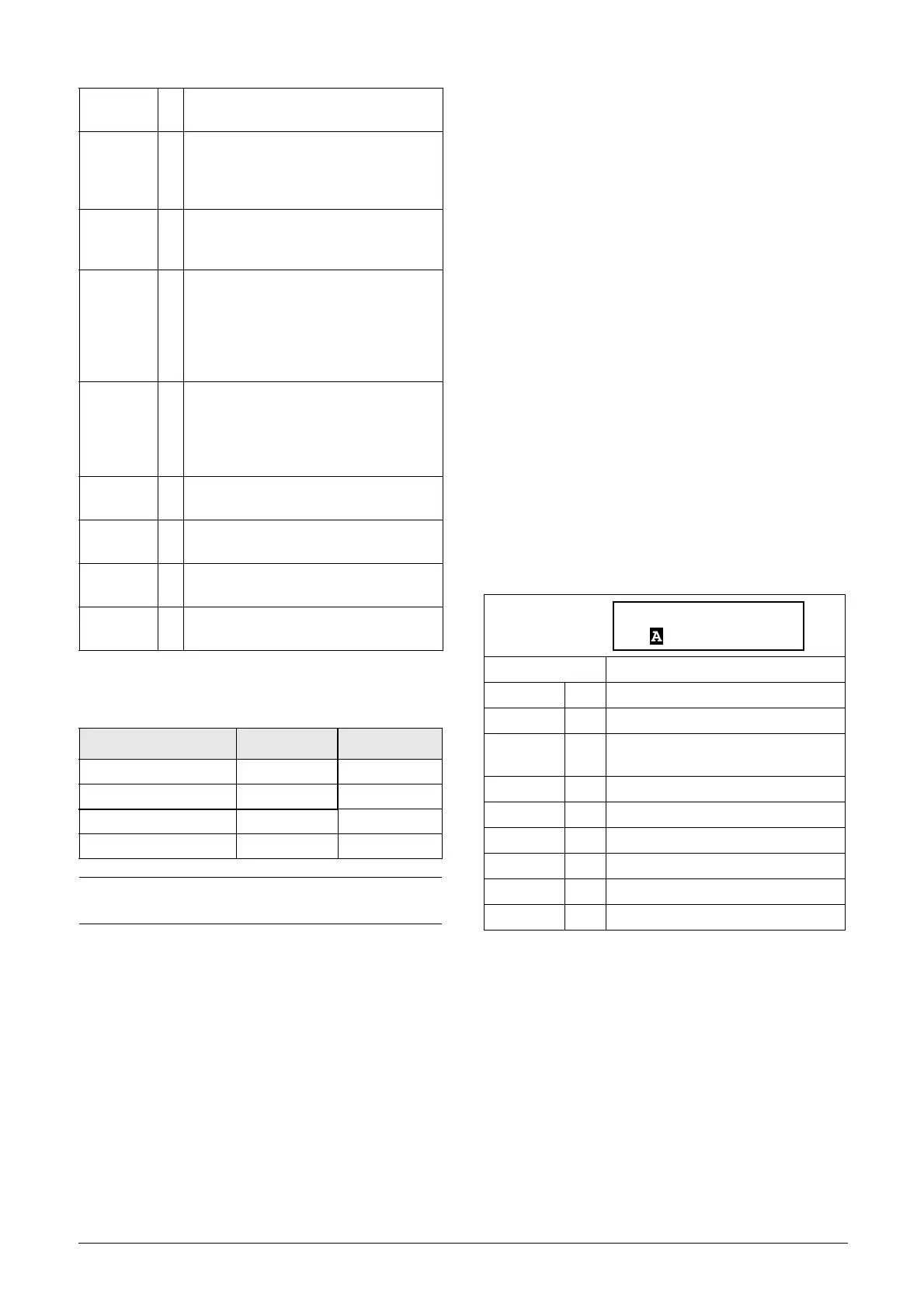
Ta b l e 2 9
Parameter Set Set Ctrl 1 Set Ctrl 2
A00
B10
C01
D11
NOTE: To activate the parameter set selection, menu
241 must be set to DigIn.
Default: Current
Off 0 Analogue output not active.
Torque 2 Actual torque.
Process Val 3
Actual process value according to
Process feedback signal.
Shaft Power 4 Actual shaft power.
Current 6 Actual current.
El power 7 Actual electrical power.
AnIn 10 Mirror of received signal value on AnIn.
Line Voltage 14 Mains supply
Used Th Cap 15 Used thermal capacity
 Loading...
