CG Drives & Automation, 01-5980-01r2 Operation via the control panel 43
6. Operation via the control panel
The control panel displays the status of the softstarter and is
used to set all the parameters. It is also possible to control
the motor directly from the control panel.
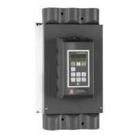
Fig. 29 Control panel
6.1 Display
The display is back lit and consists of 2 rows, each with
space for 16 characters. The display is divided into six areas.
The different areas in the display are described below:
Fig. 30 LC display
NOTE: The language in the display is as default set to
English. To conform with the content of the Instruction
manual change language in menu [211].
LCD display
LEDs
Control keys
Toggle key
Function keys
Area A: Shows the actual menu number (3 or 4 digits).
Area B:
Shows if the menu is in the Toggle loop
(page 46), indicated with , and/or if the softs-
tarter is set for “Local” operation (page 47), indi-
cated with .
Area C:
Shows the abbreviated name of the active menu,
e.g. menu or description of the contents.
Area D:
Shows the status of the softstarter (3 charac-
ters).
The following status indications are possible:
Acc: Motor accellerating
Dec: Motor decellerating
I
2
t: Active I
2
t motor protection
Run: Motor runs at full speed
Jog: Motor runs at jog speed
Trp: Tripped
Stp: Motor is stopped
Area E:
Shows active parameter set: , , , or ;
and if it is a motor parameter: M1, M2, M3, or
M4.
Shows a flashing cursor when altering a menu
parameter.
Also shows “S” to indicate soft trip, and “A” if
max number of autoreset attempts is exceeded.
Area F:
Shows the setting or selection in the active
menu (empty at 1st level and 2nd level menus).
Shows warnings and alarm messages.
221 T Motor Volt
Stp
A M1 400V

 Loading...