22 Connections CG Drives & Automation 01-5980-01r2
3.3 Control signal connections
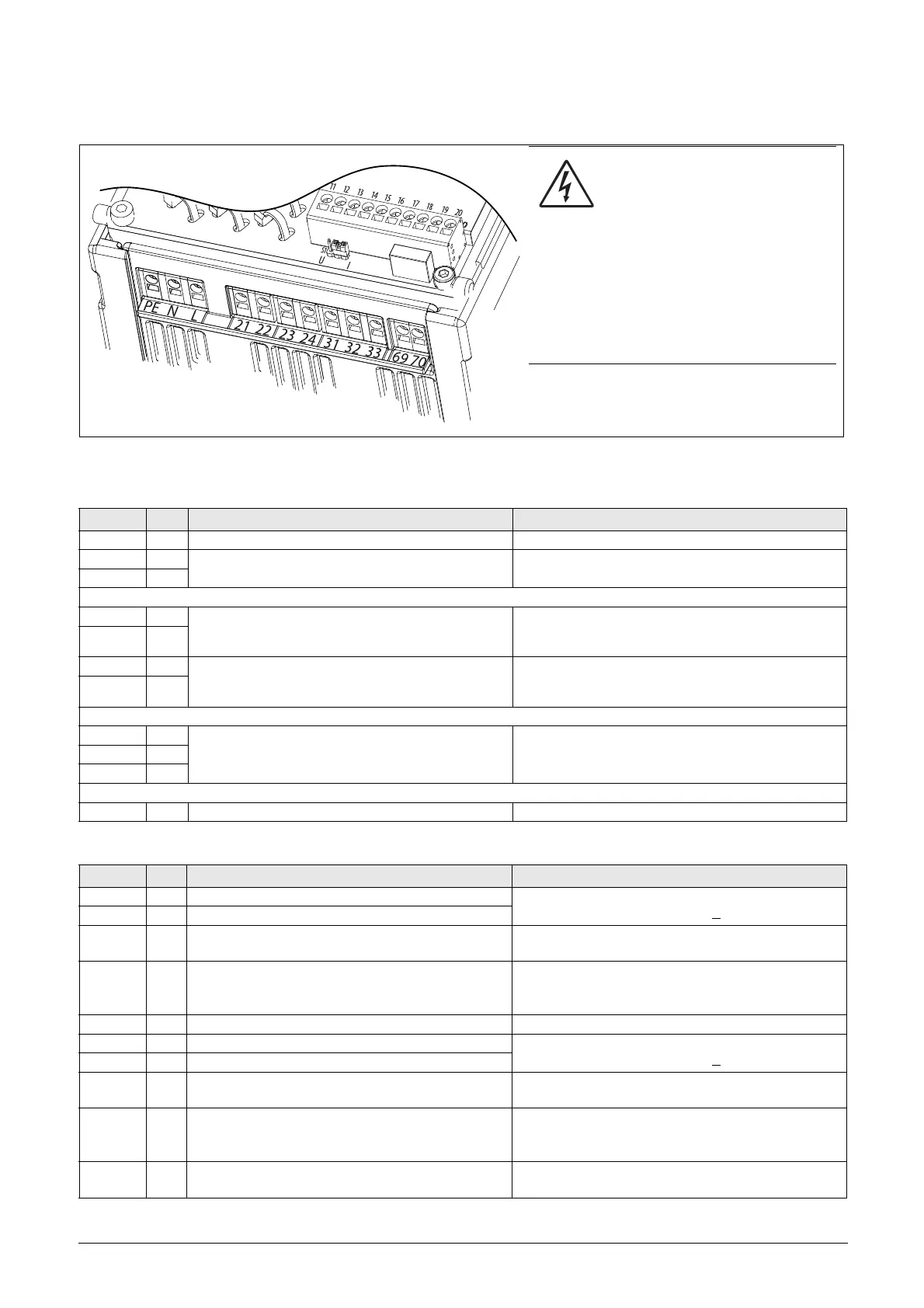
Fig. 18 Control board and power board connections.
WARNING!
The relay terminals 21-33 are single
isolated. Do NOT mix SELV voltage
with e.g. 230 VAC on these
terminals.
A solution when dealing with mixed SELV/
system voltage signals is to install an
additional I/O board option ( see Chapter 12.3
page 155) and connect all SELV voltage signals
to the relay terminals of this option board while
connecting all 230VAC signals to the power
board relay terminals 21 - 33.
Table 12 Power board connections
Terminal Function Electrical characteristics
PE Protective Earth Protective grounding
N
Control supply voltage 100-240 VAC ±10%
L
21 NO Programmable relay 1. Factory setting is “Operation”
with indication by closing contact on terminals 21 to
22.
1-pole closing contact (NO), 250 VAC 8 A or 24 VDC 8 A
resistive, 250 VAC, 3 A inductive. Min. 100 mA.
See Warning.
22 C
23 NO
Programmable relay 2. Factory setting is “Off” with
indication by closing contact on terminals 23 to 24.
1-pole closing contact (NO), 250 VAC 8 A or 24 VDC 8 A
resistive, 250 VAC, 3 A inductive. Min. 100 mA.
See Warning.
24 C
31 NO
Programmable relay 3. Factory setting is “Trip”.
Indication by closing contact on terminals 31 to 32
and opening contact on 32 to 33.
1-pole change-over contact (NO/NC), 250 VAC 8A or 24
VDC 8A resistive, 250 VAC, 3A inductive. Min. 100 mA.
See Warning.
32 C
33 NC
69-70 PTC Thermistor input Alarm level 2.4 kΩ. Switch back level 2.2 kΩ.
Table 13 Control board connections
Terminal Function Electrical characteristics
11 Digital input 1. Factory setting is “Run FWD”
0-4 V --> 0; 8-27 V--> 1. Max. 37 V for 10 sec.
Impedance: <3.3 VDC: 4.7 kΩ. - >
3.3 VDC: 3.6 kΩ
12 Digital input 2. Factory setting is “Stop”.
13 Control signal supply voltage to analogue input.
+10 VDC ±5%. Max. current from +10 VDC: 10 mA.
Short circuit-proof and overload-proof.
14
Analogue input, 0-10 V, 2-10 V, 0-20 mA and
4-20 mA. Factory setting is “4-20 mA”.
S1 jumper for U/I selection.
Impedance to terminal 15 (0 VDC) voltage signal:
20 kΩ, current signal: 250 Ω.
15 GND (common) 0 VDC signal ground
16 Digital input 3. Factory setting is “Set Ctrl 1”
0-4 V --> 0; 8-27 V--> 1. Max. 37 V for 10 sec.
Impedance: <3.3 VDC: 4.7 kΩ. - >3.3 VDC: 3.6 kΩ
17 Digital input 4. Factory setting is “Reset”
18 Control signal supply 1, voltage to digital input.
+24 VDC ±5%. Max. current from +24 VDC = 50 mA.
Short circuit-proof and overload-proof.
19 Analogue output. Factory setting is “Current”.
Analogue output contact:
0-10 V, 2-10 V; min load impedance 700 Ω
0-20 mA and 4-20 mA; max load impedance 500 Ω
20 Control signal supply 2, voltage to digital input.
+24 VDC ±5%. Max. current from +24 VDC = 50 mA.
Short circuit-proof and overload-proof.

 Loading...